This episode is part of the ‘Web Guiding Applications and Advanced Web Guiding Concepts’ series and focuses on advanced edge guiding techniques, specifically single edge web guiding. The video explains the use of web guides and edge sensors for feedback in guiding mechanisms. It covers the positioning of sensors, the importance of alignment, and the common practice of repositioning sensors during web width changes. The episode also addresses potential operator errors and their impact on web guiding performance during product changeovers.
Transcript
Show full transcript (280 words)
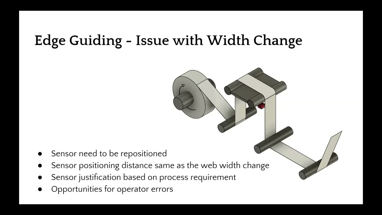
So in terms of edge guiding, most of you are familiar with this. We have a web guide and an edge sensor to provide feedback for the web guide mechanism. Last month we talked about the guiding principles and fundamentals of it. But essentially in most machines in edgeguiding kind of an application you position the sensor either on the operator side or on the drive side drive or the gear side and then the web is guided to the middle of the sensor position and the sensor is positioned along the cross machine direction so that the alignment provides the required justification of the web.
The main thing with this kind of a system is that it works well for most cases and for maybe majority of the applications there's no issue with it. The main issue comes when we have to change the web width. Whenever there is a product change over and you do a web width change the sensor has to be repositioned. As we get narrower, the sensor has to be moved to a different location.
That location of the sensor has to be justified based on the process requirement. In these examples, the sensors were moved so that the web center line position is always the same irrespective of the web width. But in certain other applications, it may be necessary to justify along the operator side or maybe along the drive side. So that is the only thing someone has to do in terms of product change over is to move the sensor.
But moving the sensor creates opportunities for operator errors and this can have other consequences with the web guiding performance.
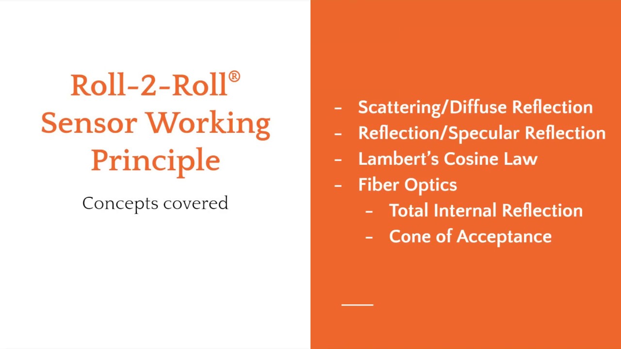
The webinar will cover sensing and measurement technology that are used in Roll-2-Roll® Sensors.
The presentation will cover:
- the fundamental working principle of the patented fiber optic technology
- how it differs from the conventional sensors
- benefits of the fiber optic technology
- application of the fiber optic sensor technology for sensing and measurement applications such as edge detection, width measurement, registration mark detection, flag detection, void/hole detection, tear detection, etc.
Transcript
Show full transcript (9115 words)
talk a little bit about the different sensors that are available in the market and how our sensor is different and then we'll also talk about what are the applications for our sensor in this industry so to start off with just to give you an idea on some of the topics that we cover most often when we are looking at edge sensing a lot of the sensors that we use are going to be optical sensors but the some of the concepts that we have covered here doesn't really only apply to just optical sensors it can also be sound or any kind of a wave so some of the basic concepts that we are going to be looking at and is what is reflection what is absorption what is transmission and how the conventional sensors use these concepts to determine the web position and while we are going through this presentation you will also have some polls that will be administered you should be able to see the pulse and if you can answer those that would be really helpful for us so that it cannot guide us through this process I also have Carlo and Pedro Manning the polls in the Q&A section so any time there is some question or things like that feel free to put your questions there and they will be able to address that so in terms of concepts let's take a look at these so reflection so we have a light source that is being incident on an object and what can that light do well basically there are three main things that can happen to the light source the light can be transmitted through the object most of the time if the material is optically transparent or translucent there is some amount of the light or radiation for that matter which actually goes through the object some amount of light would be absorbed when the light is absorbed this is mainly because the photon the photons interact with the object and they would get absorbed into the object and this may be dissipated in the form of heat or even fluorescence then some amount of light would be reflected and basically the reflection is whatever the light that is incident on the object that is returned back to the same medium that is called as reflection here the the object is usually a different medium it could be a solid it could be a liquid whatever it may be and then where this incident light is that's another different medium it could be air or it could be vacuum or any of those so the reflection is basically returning the light back to the original medium transmission is basically passage of light through the medium an absorption is actually absorption of the light into the medium the reflection and transmission typically do not change the light frequency when we say frequency it's more like color so if you have a red light and the light goes through an object or it gets reflected the color typically does not change there are special cases when it will change but usually it doesn't change and then absorption is basically the light is absorbed into the material and sometimes the absorbed light will actually change the state of the material and it can cause further emissions and those are called fluorescence these are something that you would see with ultraviolet light source and when they fall on a certain type of object the object actually absorbs the light in the ultraviolet frequency range then that absorbed material gets to an excited state and then that emits a light in a different frequency usually called fluorescence so most sensors use or most optical sensors use these these three phenomena to kind of figure out how to detect the web so actually how it happens is is based on the amount of light that is transmitted or reflected or absorbed and there is a term for those and that's called reflectance which is the ratio of the light reflected to the incident light transmittance is the ratio of the transmitted to the incident radiation and an absorption is the ratio of the light absorbed to the incident radiation the reflection reflectance and transmittance or usually used to define optical properties of material so if a material is optically transparent that means that it transmits a lot of light through the object or it also reflects a little bit of light through the object that's what it means to be an optically transparent material while on the other hand if a material is opaque that means that the the object is going to reflect most of the light and it's going to transmit very little if not none of the light that is falling on the object so most often I mean almost all cases the color that we perceive on an object is because of selective absorption so if you see an object to be green that means that that object absorbs all bay links of light except green which is reflected out and that's why we are able to see the object at screen now all of these depend upon the wavelength of light certain objects behave differently based on the wavelength of light a great example is x-ray which is also a radiation x-ray may pass through opaque objects which are opaque the visible spectrum but are actually not opaque in the x-rays wavelength like wise and transparent object may not really be transparent in a different wavelength such as an infrared that's one of the reasons why our infrared sensor can even work with transparent webs transparent materials so these are the basic concepts in terms of how light interact with an object or what happens when light falls on an object most sensors use this principle so this is one of the most common sensor used in edge detection and it's called an opposing beam sensor essentially what it is is that the sensor has got two sides to it a transmitter and a receiver the transmitter sends some kind of a signal could be light sound or it could even be air just for our case we will just limit it to light and sound and then the receiver and in in the end and that signal is being transmitted or absorbed by the material and then the remaining signal falls on the receiver so this this technology or this sensing principle works well when the material absorbs the light or the signal like what we have shown here so none of the light sources that is falling on this web material is actually transmitted so you can basically infer the position by looking at how much light that I get or let's say if the receiver gets 50% of the light then it means that the web is at 50% of the viewing area that's where it is it's really simple sensor technology and usually it's also referred with different names it's called fork-style or a u-shape sensor or a blocking and unblocking sensor technology now like I said most often this sensor technology works but there are some cases when it does and work well and as you can imagine whenever the web material starts to have high transmittance then the signal is going to leak through it and the sensor will provide a different output now if you compare these two web materials they are exactly at the same location but because of the properties of the material you're going to have different transmittance and that really affects the sensor output and that's the main shortcoming of these types of material now how does it how does it involve how does it relate to our cases basically if the material is porous that means that actually there is no solid there to prevent that light to go through or sound to go through then that's a problem obviously if it is opaque sorry um the opacity is lower then that's a problem and this means that the sensor requires calibration and since this is an inferred measurement let's say you are you get 50 percent signal that means you assume you're at 50 percent location this is not an absolute measurement so you really don't know unless you calibrate it what the actual position is and it's not accurate that's the main thing with it there's also ambiguity in spatial ambiguity with this kind of a sensor sensor technology I'll talk a little bit about it in the next slide about what what I mean by that now there are other types of sensors that try to avoid the issue with transmittance and the way they do it is what is called as a retro-reflective sensors you have a transmitter and receiver on the same side there is no receiver on the opposite side the light is now incident on the reflector the reflector is a special material so it reflects the light back to the receiver and when we do that the portion of the light that goes through the material is attenuated here and then it falls on the reflector and now all the light that is falling on the reflector is reflected back to the receiver and the light that actually goes through the material it's actually attenuated twice as much as if you had a transmitter and receiver on these two sides so the main advantage with this kind of a system is that you are essentially doubling the or essentially reducing the transmittance by half by making your light go back and forth twice through the same material so if you have like an clear material you might be able to do this where you can increase the sensitivity of your system and then you can you can use the retro-reflective technique to detect the web the other advantage of this kind of system is that the transmitter and the receiver are on the same side and then the reflector could be much farther away from the transmitter and receiver so that essentially make this like a one-sided system and this has other advantages in terms of like you don't have to have a constrainted fork where where the the throat of the fork you don't have to worry about that if the web plane changes and things like that and it's usually compact most often these retro-reflective sensors are used for in presence/absence detection and there are some sensors that are used for nonwoven applications and they actually use a special mirror kind of a thing so that it can go through low basis weight nonwoven a couple of times before we can get the signal back so that's a retro-reflective sensor now the main thing with the conventional ed sensors is that it's a simple sensor technology when you have low transmittance but as soon as you start looking at materials that have special properties and things like that these sensors have issues especially with engineered materials like nonwovens and and some really clear material the material properties affects transmissions and absorption and hence the accuracy of the sensor is lost now I talked about spatial ambiguity let's say the receiver is a single element maybe it's an ultrasonic receiver with just a one element or maybe a photocell if that's the case then if you have a small object like this which is much smaller compared to the viewing area of the sensor and if the object is anywhere within this range there's no way the sensor can tell you what the position is it can tell how much signal attackin teammates but it cannot tell what the position is and that's what is called as spatial ambiguity with these kind of sensors these are especially important when we look at threads and things like that with our sensor that's not an issue the other thing with these sensors is it cannot detect surface characteristics so it the the whole web either blocks or transmits and since there is no way we can figure out if there's a feature on the web or a structure on the web there's no way this sensor technology can detect what it is the other issues that these technologies have is that image saturation issues basically what it means is that most often the receiver is saturated by light and then you have a let's say you have a small object that is there that photo cell or the pixal for that matter might be saturated and it would have some kind of a saturation issue with that so when you are trying to detect a small object or a feature there is a problem then finally the sensor resolution and depends upon the range of the sensor so if it is a single receiver element and you want to make this sensor 2 inches wide then the resolution that it can detect is going to be the same as set a solution of the A to D converter or whatever it may be so irrespective of the width of the sensor or the range of the sensor the resolution would change and that's an issue now instead of using transmittance can we use reflection of the web to measure the web position and the answer is yes we can and that's what we do with our sensor and in order to look at that let's take a look at a few concepts about basically reflection or scattering or diffuse reflection and a couple of different things that we use in our sensor technology and then our sensor is based on optical fibers and optical fiber properties or fiber optics so we'll look at a couple of concept there as well so again we have an incident light that is falling on an object and we talked about reflection transmittance and absorption actually this reflection was just like a simpler way of representation of the light the light source is going to be it's not it's not going to be like a ray it's going to be a wave in fact so what really happens is that the light falling on the object it's actually scattering everywhere and the light goes off everywhere and then there's a portion of the light that is reflected now this phenomenon where it scatters off everywhere it's called scattering or the actual technical term for that is diffuse reflection and then this ray right here which is following the typical ray optics is called specular reflection so you have specular reflection and then diffuse reflection specular reflection is usually seen in smooth surfaces polished surfaces mirrors and things like that where the light will bounce at the same angle as the incident angle and scattering and diffuse reflection is going to be seen in most materials that are not polished or smooth so almost every material that we deal with is doing the few scattering and the reason why we are able to see a color in an object on an object is because of scattering or diffuse scattering so the the reason why this is scattering in all these direction is because the surface has got irregularities on it and those irregularities have different angles and when the incident light falls on that microscopic irregularity its reflecting it back at the same angle with respect to that small microscopic surface but because we have a whole bunch of those the light is scattered in all the different direction just like scattering and reflection there's also diffuse reflection and regular sorry diffuse transmittance and regular transmittance when the light goes to it and that is not of importance for us the main thing for us is this reflection now there is another thing that is important when you're installing the sensor we talk about the angle this is mainly saying that if you have a light source that is coming at a certain angle then the maximum amount of scattering is going to happen close to the normal when we do our sensor installation there are some sense of installation recommendation that we provide that's that's mainly based on this so if you have if you want to view the object from this angle then as you can see here there's going to be a lot less light than if you view from here and likewise the light source as well this is called as Lambert's cosine law and basically you want to keep that angle as close to normal as possible so that we can get the maximum so if we use scattering how do we make a sensor that can do this again and just like a retroreflector one we have a light source and a transmitter and a receiver the the light goes through here falls on the web if the web material was perfectly reflective then all the light that goes here will exactly reflect back at the same angle which is normal to the surface and then we will have a really good image and we'll be happy but that's not what happens the light when it falls on the material it's just chaotic it's going to reflect everywhere or scatter everywhere and we're going to have the same issue like an opposing beam sensor technology where we have scattering and which will be dependent upon the material and how far the material is from the web and and the spatial ambiguity and accuracy and things like that so how do we fix that basically we add a filter to it and that's our proprietary technology so we add a filter that filters the light and the way it works is that when the light falls on the web it scatters everywhere but the filter is going to selectively couple the light coming in falling on it at a certain angle and now the light goes back now we know where the web is if this receiver is a pixel array or some kind of imaging element then we would know all these elements would receive light and all these elements would be dark and if we do an edge detection algorithm we can figure out where the web is that's the underlying principle of that and how do we create a filter that's based on fiber optics so optical fibers have special properties in that they allow the light to go in only at a certain angle like the cone that is shown here so if you have the web if you have the light falling on the fiber at an angle that is steeper than the scone it will not go in so it's basically gonna filter out all the light and allow light only coming at a certain angle to go in and that's how we do it so that's the basic fiber optic technology that we have so how does it work just to give you an illustration there's a light source that is illuminating the web and the light scatters everywhere but then the light that is directly underneath the fiber is the one that gets coupled into the fiber all the other light that is coming at an angle doesn't get coupled into the fiber and that's how we we we didn't mind what the web position is again this is a true and absolute web position measurement because the fiber has to align with the web edge for it to be able to pick up the light and just just an illustration of how we do it now essentially the light source angle can be at any angle as we saw before but we want to keep the scattering to the maximum so we're going to keep that light source as close to the receiver as possible to take advantage of the Lambert's in my inverse Lambert's cosine law so we have a light source it could be laser LED or anything like that it falls on the surface it scatters everywhere this is a side view of the optics and this is the front view of the same thing so the light falls onto the fiber optics and then the photo diode or a pixel which is position behind the fiber optics is going to pick up that light that's how we determine where the position of the web is now I mentioned that we have a pixel or a photodiode behind the fiber basically what we do is we capture the image and then we do real-time image processing to determine the edge of the material this is an important part of our sensor technology technology not just that not just the the way the sensor works but also how do we process the image is important the algorithm adapts to a few other things that we will talk about later in terms of how do you adjust for intensity changes how do you adjust for focal lengths and stuff like that so essentially a component the components of our sensor or four main components one is the light source we typically use LED light source it could be visible or a broad light spectrum or infrared or even UV light and then there is an optics that is filtering the light that is coming at all different angles that is our patented fiber-optic technology and then there is an imaging element behind that optics which is usually a linear pixel array and it's anywhere from 768 pixels to about 14,000 pixels and these pixels are arranged really close to each other at 63 and 1/2 micron or about five thousandth of an inch and then finally the image processing algorithm which actually does the edge detection so let's see how that works now we have a different samples of web that we can present to our sensor as you can see the some of them are opaque some of them are completely optically transferring some of them are porous they have voids in them and irrespective of any of those our sensor can provide a really reliable and highly accurate web position measurement I think this is a published article that you can find in converting but the but dearest the accuracy was about ninety over ninety nine point three percent with any of those materials and we didn't do any calibration that's the main thing with our sensor technology now just to give you an idea we saw the different images as you can see the light that is falling on to the imaging element is going to have varying intensity depending upon the material that we have so if we have a light scale where blue is completely dark and red is completely light or white and then there's a spectrum going through that you can see that all of these edges are are not as sharp as what we have illustrated in the working principle in spite of that this is the output of the edge detection algorithm they did the edge detection algorithm goes in and says oh this is the edge for this black nonwoven web this is the edge for the transparent web this is the edge for the load GSM nonwoven and this is the edge for the perla now we don't really just have to look at the edge of the material we can actually look at features or patterns on the material as long as the pattern is parallel to the machine direction then we can do the same thing so here for example we had some die cut edge of a label so we wanted to detect the edge right here edge right here edge right here on the edge right here so and again we can do that with our sensor technology and it provides a pretty good measurement so in terms of the the image processing feature that we have the key things there are we do what we call as dynamic threshold that means that every single image that we take every sample we do run our edge detection algorithm and it automatically to the lighting it adjust automatically to the focus it adjust automatically to the material and figure out figures out where the edges and just to give you an example again this is an image from our four 440 sensor with infrared light source black just means that there is no light coming back and then white means that it's coming back now this is the raw image on the top we presented a burlap web right there and if we just say I don't care about what's in between I just need the edge of the web tell me the left edge in the right edge then we can give an output which is going to be like this so the edge detection algorithm goes in and picks up the left edge in the right edge it doesn't care about anything in the middle now what happens if we have a lower brightness it's the same web same location we have a lower brightness as you can see these two images are pretty different with low intensity again no problem no setup no calibration the edge detection algorithm will automatically adapt to that and pick that and what happens if you have a really bad image where it's not only low brightness but it's also further away from our sensor no problem we can still do that I'm not sure if you can see this on your screen but this is really faint gradient here but we can still do that now the other things that we can also do is background suppression what it means is that we have special way of adjusting automatically so that if there is a background in the image which is at a certain distance from the web we can still adjust for it and that's what is shown here so here this is an example of a clear web with an infrared light source on it and there's some background there and we were able to automatically adjust it and provide the edge positions there now when we do this we also have additional information that we provide from our sensor we can provide an edge quality feedback that means we can say how good the edges we call it as a quality factor we can provide it for each edge that we measure and then we can also provide a flutter feedback for each edge again the quality factor is based on instantaneous measurement while a flutter is based on temporal it's a function of time so but anyway we can provide that flutter information as well now other things that we could do is one of the things with the with the conventional sensor is that it has issues with spatial ambiguity this is going to be common when you have like really small feature our sensor obviously does not have that issue and just to give you an example here is an image of a single thread this thread is like two or three millimeters wide and we can pick up a single thread like that with our sensor and and what if you have multiple threads and let's say you are running some kind of an operation where you have to guide or bring in multiple threads into your process and you want to be able to count the threads well if you present something like that we can still do that as you can see in the raw image there are some threads which are kind of out of focus or farther away some really in focus and a it doesn't matter our algorithm is able to go in and pick that up and tell you process the image and tell you the edges now when we do edge detection like this we can essentially provide you with every single edge position where they are within the sensor or most often because it's a lot of data that is going through we can actually provide you some statistics of this whole measurement so we can say well what is the average width of these threads that we picked up and what is the average gap between them so on and so forth what is the minimum what is the maximum so we can compress that in the data and provide some statistics that you can use to kind of figure it out like for example here these there are actually two threads here these two threads are really close to each other and when they are close to each other then this kind of the thread kind of became like double so if you're able to monitor that then we can figure that out and tell you that hey something is coming too close to each other or overlapping and things like that again we can with low brightness it's not an issue we can still pick up that edge right there now I talked about edges but it doesn't have to be an edge here this is basically a printed pattern that we are looking at different colors different colors are going to reflect light at different intensity again an infrared light source is illuminating a colored web here and you can see that it can pick up these contrasts so when we do contrast application what we can do is we can not only tell you the location of the edge where the the contrast is different but we can also tell you the intensity of that so that's how we can teach our sensor to follow a particular color or a line or something like that now we we have done sub-pixel edge detection so that means that we can go to one twenty thousandth of an inch or sixteen micron in terms of the resolution our standard pixels or the standard imaging element has a resolution of 63 and a half micron and we can do 1/4 or 1/8 of that to get sub pixel resolution so those are the features of our sensor in terms of the sensing principle how we do image processing and how the raw image looks like and how the process image looks like and things like that now let me just quickly go over some of the applications that we have with our sensor first and foremost we do edge detection that's one of the basic things if we want to do edge guiding then we need to do edge detection the other things that we do are with the measurement contrast position measurement contrast position detection and contrast our pattern it's pretty much the same kind of thing then we do thread counting and I showed a little bit about that we can also detect a mark on the web we can also detect a flag on the web we can also detect what we call as a coverage or the for lack of a better term optical density of the web and then finally the stack measurement so let's go over some of these really quick edge detection since our sensor is one-sided you can have a web that is coming from left to right like in this case or from right to left it doesn't matter all we just need to know is what direction we need to scan for the edge if if if the sent if if the sensor if we're looking at the right edge of the web which is this one then we're going to scan from right to left if we're looking at the left of the left edge of the web then wicker we're going to scan for from left to right now what we are going to look for is in an edge detection is the first transition from a dark to any kind of a light and that's how we would do the edge detection now I've got a short video here and hopefully it can play properly and these videos are on our website but the idea here is to show that we can put any web material and this is showing the position of the web we can pretty much put any web material and without any setup or calibration we can get the true measurement or the absolute measurement of the web this is like a highly porous non woven that we used the other extreme example is like a really porous mesh kind of a web even if we have a web like that when we do edge detection we can accurately get the leftmost edge of the web or whatever the edge that we want we can get that accurately so that's what this video is showing so some application example where we provide the most value to our customers is that whenever you are doing edge detection with frequent material change over like if you are going to detect a paper web all day every day yeah we can do that too but that's not where our value is this would be like nonwovens or any any kind of engineered material that you are changing quite frequently where you don't know the opacity and the porosity and stuff like that our sensors work great in those application or if we do width changes like I mentioned we can go from about 48 millimeters up to about 900 millimeters in sensing range without losing any resolution that means that you can run different webs without different width webs without needing to move the sensor that's another place where we have a pretty good advantage challenging materials of course that's that's our specialty is if you have something that's really complex then we can do that and then challenging environments specifically vacuum that's a place where we have got a lot of success especially when we are trying to detect clear film inside a vacuum environment now the advantages are that we don't need any setup for calibration and it's pretty cost effective in terms of connectivity we have industrial Ethernet this could be Ethernet IP or pro finet will also have EtherCAT and other things that we could do as well and some unique applications like I said clear web inside a vacuum this is pretty unique just because of the fact that most current technologies for detecting clear film or ultrasonic and ultrasonic doesn't work inside vacuum so that's pretty unique for us and then again metals that's another place where metals inside vacuum is another one since our sensor is single sided we have successfully used our sensor in abrasive environments where a web flutter or something like that they typically knock off a fork style sensor and we can position our sensor farther away from the web because our algorithm can adapt to that and we were able to do that with an abrasive web environment and then you can also do width measurement on low basis weight non-roman this is usually a problem with current sensors because they are not they're really really you need to do a lot of filtering with that or it could be some kind of an edge that is kind of ragged and we can also do like detecting ridges on a web so this could be some kind of an extruded plastic or something that has got a three-dimensional structure on it and you want to follow or see that some of those things we could do just to give you an idea the the the the sensor itself has just the optics the imaging element and the light source it doesn't have the processing so you need a sensor and a controller to do that it shows and then different output options at the hint we can have for edge sensing usually we can to analog output if you want to connect it to some legacy systems that use analog sensors otherwise we prefer to provide Ethernet IP or Pro finet for that matter option for H as output now the other common application that we do is width measurement now width measurement with two sensors or one sensor obviously this sensor is too small and if the WebWork changes then you're going to have an issue that's where we have our value where we can provide a wider sensor and what you don't have to have the sensors mounted on some kind of a linear positioners mechanical positioners these are again cost prohibitive and have inaccuracies and all those kind of things so you can avoid all of those by using a wider sensor and when the web which changes the sensor doesn't move so it can still detect the web width now if the sensor is wide enough then we can measure both edges of the web with a single sensor again this having a single sensor that does all of those then you don't have to worry about alignment the distance between the two sensors and all those kind of things this is the reason why we are moving to wider and wider sensors every year and we are about to release our 900 millimeter wide sensor this summer anyway if you have a wide sensor then you can see both edges of the web and without having any issues now most of the time these are applications in shrink sleeve so this is a one of the video from our distributor in Mexico but as you can see one of the things apart from providing accuracy and resolution in width measurement it's a safety thing so you don't really have to have somebody go in and measure a web while it's moving to make sure that it's at the site the correct width you can have an automatic automated system that can do that so here we're showing our for 40 mm sensor that is looking at both edges of the web in a shrink sleeve or a folding web application now we can do the same thing for others and some of the common applications are if you want to look at a blown film and you want to measure the width of the tube lay-flat width of the tube of the blown film a lots of different applications again this is one of our videos from our distributor in Mexico so like I said width measurement where we see it where where it's used like any time you are slitting and let's say you're slitting something that is uh that that requires you to measure the width to verify that we can use that folding the web again it could be in swing sleeve it could be other folding web applications and sometimes you can also look at the trim width just to make sure that you don't run too far out to the trim I mentioned about blown film and then extrusion like you can use it for monitoring extruded webs like resealable zippers or things like that that's where we we have our sensors installed and then you can also look at like width of tire rubber and in that case we can we actually have it in a back roller and we can do that as long as there is a contrast difference between the edge of the web and the background it doesn't have to be a clear background or a free space it can be anything then we can do that again different output options we typically prefer ethernet/ip or or or some kind of a industrial Ethernet apart from looking at the edge of the web we can look at contrasting features so basically we're taking advantage of the fact that different colors are gonna scatter light at different intensity in this case we are showing a white light a white light is typically used when we want to bring out visible contrast it doesn't have to be white light it can be UV so that you can have a fluorescence or can be IR as long as you are able to see the contrast difference and the light source is mainly used to extenuate the contrasting feature so either depending upon the frequency of the light source or sometimes the angle as well so some applications would be like if you want to look at a coated edge and you want to see how far the coating is to the edge lithium ion battery or any kind of coating that you can do even just regular paper coating you can do that and in paper coating case you would probably use a UV light so that most often that coating on the paper has some UV fluorescence to it or it can also be like looking at maybe tabs or things like that on a conveyor we can do that too and then not only are we detecting the contrast we can also provide the position of the contrast so you can use it for control purposes as well I've got a couple of videos here but I'm gonna skip that and you might be able to see that in our in our website I think I talked about this quickly so anytime you are guiding in a slitter where you want to slit to a printed line that's an application that could be in a doctor machine as well if you want to follow a UV line then cording width measurement and then some other simple inspection applications here's a quick video where we have a application where our sensor is installed to look at this bag which has an extrusion which is clear and then the bag itself is opaque the the idea is to measure the width of the green part of it and disregard the clear part of it and we are able to do that in this case it was installed with the free space at the back but it doesn't have to be free space you can actually install it with the back roller on it here we have an example of our sensor used to detect the width of the web where the web is supported on a roller and there is a contrast difference between the roller and the web and it's it's not clear here but we use a white light source in this one and we're actually looking for the edge of the clear film and not the edge of the printing and with the light source and we can do that and this is made this one is for width measurement for detecting wrinkles so whenever you have a wrinkle on the web that's going to reduce the width wrinkle or a fold over that's going to reduce the width and we can use our sensors to measure that there or like I said in the other application would be like if you have a tire width measurement application you have two sensors that are mounted and it can look at that the tire and in this case they they were kind of a little bit creative about it and they put a background that is white and then the tire by itself is black and the reason why it's black it's because it's absorbing all the light so in order for us to detect this we need to have a white background and then and then a clear a black foreground which is our web then we were able to detect that so that's our common width measurement application I briefly went over this this is another thing that we do is like string thread fiber monitoring so it could be like things that you use in textile and waist bands or or carbon fiber applications where you want to accurately measure multiple webs and in this case we would be able to do measure and count and provide statistics on what is the minimum what is the maximum what is the gap so on and so forth and we can also provide additional information like that again I'm going to skip this video for the sake of time and like I mentioned it's elastic thread or textile or carbon fiber any of those the main advantage here is that we're replacing some camera based system with our sensor and then for thread detection we are replacing mechanical pulleys and and pressure-sensitive sensors and we can actually stitch together multiple sensors over Ethernet our 440 sensors we have installed it up to 2 meters wide where we have connected four of them together which is possible the next application is marked detection so again we're trying to look for a contrasting mark which is a which is going to have different scattering and we can do that the main difference here is that the mark is along the machine direction sorry if it's it goes faster it's not a consistent mark that comes and as in a printed pattern or things like that but it doesn't matter we can still detect that and it can be a visible mark or UV fluorescent mark any of those and it's not only that we can detect the mark we can actually track the mark in terms of position that means that we're not just saying giving you an on-off signal we can also provide an analog output that tells you where the mark is with respect to the sensor the main advantage there is that we have a wider sensor so if the web moves we can still track the mark we can also detect flags on the web so let's say you have a web and it's got multiple flags you are going into a slitter now you're going to remove all the flags and then you're going to another process and then you want to put the flag back in how do you do that then you can detect a flag and then have some kind of a thing that would put the flag back in again after you complete it this is a little bit even though that you can see that the flags are different colors different weights different sizes the web may be different we can do all of those without any need for teaching I can adapt to different flags and different webs and it is not affected by web wander or web moving back and forth then we can also provide a quality signal in that case we can also do tear detection or coverage this is just an illustration or example of let's say there is a tear in the web and then the web actually splits we can detect that this is an exaggeration but if the tear is small we can still do that now if the web separates and moves the left and the right edge moves then that's an easier one to detect but if the web's doesn't move and you just need to see a wide or a hole again we can detect that again all of this is based on how much light we are getting when there's nothing when there's a wide or a hole or a tear if this region is going to be dark and this region is going to be white and then we can basically integrate how many pixels that are white and how many pixels that are black and that gives us the coverage and by monitoring the coverage you can detect if there's a hole or tear or anything like that one other application that we do is we could do is also product linked measurement basically what we do here is we just rotate the sensor 90 degrees and when the product is moving on a conveyor it can track the edge and it can basically say how wide the product is the main thing with this is that the sensor doesn't have to be longer than the product and then the product can run at different speeds and you don't need an external synchronization signal to be able to pick up that so that's a quick summary of some of the applications that we have just to summarize the advantage of our sensor technology is that it's accurate it's got it provides an absolute measurement it's very simple to use when you compare to like a traditional fork style sensor or maybe even a camera based sensor the resolution is not affected by range in a camera based sensor if you want to have a bigger range you have to install the camera at a certain working distance and when you do that you lose the resolution we don't have to worry about that in our case and it's a one-sided sensor so like in a camera based system you would have to install the camera or the light source the gantry all of those here it's all enclosed fully contained and because the sensor is going to be close to the web we can have a pretty good lighting control and then it's also compact in terms of installation and we have done a lot of customizations for our sensor and these would include processing speeds of up to about thousand Hertz and then we can track multiple edges there's really no limit to the number of edges we can track it's just that the information how do we send it and then sub-pixel approximations I mention that before two to eight X we can do that and we can also control the edge detection through Ethernet industrial Ethernet and then light source customization based on the application and then essentially the customisation is bringing us more and more close to a line scan camera based system but at a much lower cost and the difference is that we actually do the customization and we don't just sell the the the sensor and the imaging we actually do the processing as well unlike other line scan based systems so that's essentially my presentation and here is the contact info if you have any questions or any application or any need for sensors please let us know and I do have some questions in the Q&A section so let me just quickly go over some of those and see can your sensor technology by the way please use the Q&A section to ask any questions if you have can your sensor technology also measure a webs thickness across a sheet of material while in motion if if that's true what when a number of threads are being read in addition to placement of threads in their respective spacing can you also read the thickness yeah the the thickness we can't do that right now not in the current state we can look at what we are doing is we are taking a projection of the image a actually it's a 1d projection of the image and since thickness is going to be in the other dimension there's not a way for us to detect both at the same time so we cannot do that what types of industrial Ethernet do you utilize yeah we can use Ethernet IP Pro finet and we can also do either cat and then other other things other protocols okay what is the minimum distance between slit webs that would allow the sensor to measure the slit width of multiple webs parallel to each other okay that's a great question so if the if the if the web can scatter a lot of light then I would say we could do probably one or two millimeters and we can easily have one or two millimeter gap between the web's and be able to detect the slip web width that's something that we could do and then what is the working distance so the working distance for the sensor is really depend upon the the amount of light that is being scattered our normal working distance that we specify is about 10 millimeters it's pretty close to the web and by putting the sensor so close to the web we have a pretty good control of the lighting and that way we can we can have a pretty good image now there are applications where we have installed it more than two inches or maybe even three inches from the web surface so it really depends upon the amount of scattering but for anything that we want to do like width measurement and things like that we would we would want that distance to be within our specification so that we can provide a pretty accurate measurement and then the other thing that I forgot to mention about the width measurement is that you can measure the width in a free span or a free space but as we showed if you measure the web width on a roller if you can get the contrast difference and you can measure on a roller then that provides the most accurate measurement because you don't have to worry about focusing and things like that even though our algorithm can compensate for it but it's it's better if we can have the web stabilized let's see um gee so that's probably all the questions that I have I hope you have a had a chance to fill out our polls that be organized and if you haven't done that you can use the tab on the left to be able to see the polls and that would be really helpful for us so that we have a better understanding about what your needs are and how we can help again my name is are Arvind Seshadri and we really appreciate your time today to join us during our webinar if you go onto our website you should you should be able to see most of the stuff that I talked about today in terms of videos they should be on our website and then if you have an application and you would like to talk to us please give us a call or contact one of our distributors or sales reps in your respective region and they would be able to help you with any of your needs if there are no other questions then I will conclude this webinar once again thank you so much for your time
Web Guiding Fundamentals: Topics in this webinar
- Web guiding Terminology
- Why we need web guides?
- Types of web guides: Terminal and Intermediate web guides
- Normal entry rule
- Main components of a web guiding system
- Unwind web guide structure
- Rewind web guide structure
- Terminal web guides design and installation considerations
- Offset-pivot guide or displacement guide design and installation considerations
- Steering or remotely pivoted web guide design and installation con
Transcript
Show full transcript (10460 words)
is going to be recorded and then we will also share the link once the webinar is done so that we can you can take a look at it after afterwards I will be your presenter I am Arvind Seshadri I'm a troll to role technologies just to give you a background I have been with troll troll for almost 6 years now and before that I was at Oklahoma State University I got my PhD in mechanical and aerospace engineering specializing in dynamics and control of roll-to-roll machines so topics such as web guiding tension control registration or some of the things that are unfamiliar with as we go along in this presentation we'll also have some polls or some questions so that we get to know a little bit more about you and what are some of the problems and hopefully we can take advantage of that and guide the presentation along the way once again we're about ready to start the webinar and as part of that let me just give you a quick poll if you can answer that really quick in the next minute or so that will help me in terms of some of the topics that will be covered today and we can look at how we can tailor that to the audience so basically we just wanted to know a little bit more about your knowledge about web guiding there are some people who might have no knowledge about web guiding there are some who might just know what a web guide is how it works or some of them are well versed in being a designer they can design web guides or design web guides into their machines or some of them could be even experts that are called upon when where you have any issues with web guiding in your operation so I'll give a just a quick minute or 30 seconds to make sure that everybody had a to answer this question okay seems like we have a pretty good mix of audience here people ranging from as people with no knowledge about web guiding and also some experts and web guiding okay thank you for taking that poll that gives me a pretty good idea on how we can proceed with the presentation okay so before we start web guiding let's just look at some of the common terminologies or names that are used for web guiding web guiding is also referred to as steering some people call us tracking depending upon whether we are guiding the edge of the web or a feature on the web it might be called as edge guiding line guiding contrast guiding more technical term would be like lateral control or lateral registration these are some common terms that are used in the academia when we are talking about guiding sometimes it's also called as CD registration CD where see these stands for cross machine Direction registration and then lateral alignment and if you're from eastern part of the world in Asia it's commonly referred to as EPC or edge position control or line position control essentially all of this means the same thing that is guiding or a web guide is used to position the web at the desired cross machine direction and it is done so that we can enable efficient transport if the web is not guided then we have issues with the web crashing into the machine quality issues wastes and things like that so why do we need web guiding all their army fully mainly for reasons why we need web guiding first and foremost is that materials are not perfect you might have a poorly bound roll that is not one properly or deliberately wound row with an oscillation on it and when we are trying to feed it into your role to the old machine you need to guide it so that it aligns with your process some materials may have thickness variation this could be like gauge band variation either during coding or forming processes especially with paper mills different gauge papers may track differently or slide differently splices whenever you have change from one role to another when you are joining two roles of web it might be a step change or it might also be like an angular misalignment of the splice and then some materials have a natural curvature to them which is called as camber so the material properties when the materials are not perfect that's going to have the web miss track in your machine it could also be due to machine itself so either you have machines with out of round rollers like a crown or a concave or a convex roller whenever you have a variation in the diameter of the roller that's a problem or the rollers are not aligned properly with respect to each other that could also cause the webs to miss track you might also have tension control issues and if you don't have enough tension you don't have traction then that's going to be an issue and whenever you have acceleration or deceleration that might also cause the web to miss track it could also be due to processes for example if you have a coding process and you have uneven coding across the width of the web that's going to cause issues with tracking and also some processes where you could have air entrained between the web and the roller that would cause the web to loose fraction and miss track so that could also be an issue and that's why we need web carry finally operators mainly when they are splicing the web or when they are putting a new parent role into their roll-to-roll machine they may not Center it or they may not put it at the right location that might also cause an issue and that might need web guiding so web guides are necessary at different locations of the machine because you might need alignment at different parts of the machine so that's that's the main thing with web guiding is you have to put a web guide in front of any process that requires web alignment just to give you an example let's say you are laminating something and we have two layers of web coming in to this lamination process at this point you would need a web guide so that you can online this layer and this layer with respect to each other the guides that are used within the machine or called as intermediate guides or they are intermediate to the machine and the guides that are used at the entry and exit of the machines or call as terminal guides so we're going to look at all of these in detail but that gives you an idea of why we need web guides and where we need web guides in terms of the location as I mentioned when you have a web guide that that is located at the entry and exit of the machine they are called as terminal web guides there are lots of names for these and some of the common names are shifting stand a shifting base a shifting side lay on role positioning stands if you're in the metals industry it might be uncoil or recoil and in other industries it might be called pay off and tension real and specifically in these presentations and in our terminologies we call them as unwind and rewind guide an unwind guide is something that is at the entry of your old troll machine while a rewind guide is at the winder or the exit of a roll-to-roll machine so these are some of the terms that are used for terminal guides and in terms of intermediate guides these are the web guides that are used within the process within the machine there are certainly multiple types of these web guides and the most common one is what is called as an offset pivot guide other names for opposite favorite guides or displacement guides positive displacement guide pivot frame or a table guide the second most commonly used intermediate web guide is a remotely pivoted guide that's a technical norm at term but most commonly it's called as a steering guide or steering roller or a swivel roller and then there are other less common web guides like an pivoted guide or center pivoted guide and then even turn bars are all available well we'll take a little bit deeper look at all of these different kinds as we go along in this presentation but most of these web guides work on a basic fundamental principle and that is what we call it as normal entry so what is normal entry say normal entry is basically is a web approaching a roller will always align itself perpendicular to the axis of rotation of the roller as you see in this video right here let me restart that as soon as the the roller on the left has a misalignment the web started to track and it started to move in such a way that it will approach the roller on the Left perpendicular to the axis of the rotation this is the fundamental principle that is used in most of the intermediate web bags that we are going to see and what's happening here is that the web is essentially behaving like a beam and the angular displacement on this left-hand side is bending the team and it's causing the beam to bend and that's what it's causing the web to track to this side there are lots of dynamics involved in this process how fast the web moves how much does it move all of those depends upon the transport conditions the what type of web it is what kind of traction you have and things like that and obviously the static behavior is that at steady state once this angle is said how much is it going to move are we going to see any movement on this side as you can notice that when this web moved the upstream roller the web was still there it was maintaining there because it was able to have enough traction so that the lateral forces at the moment that is acting there was not able to make the web move and whenever we have a motion like this bending occurs bending in term means that there are stresses developed in the web so you're going to have a tight side and a slack side and there going to be a tension profile here so these are important to understand for us in order to have a successful web guiding application or execution of a web cam so in terms of a basic web guiding system we are mainly dealing with four main items apart from the web we're mainly dealing with four main items one is the guide structure or the mechanism this is the device that is actually making contact with the web and that's the one that is need to be moved or it moves the web and there are different types of guide structures that we will go through the other component of web guiding system is an actuator so actuator is something that takes an electrical signal and then it converts that into physical motion so that it moves the guide structure so that the web can be loved rated at the desired location the third and one of the most important components of a web guiding system is a sensor the sensor is the device that provides the feedback the sensor is the one that tells us where the web is where means it's inferring the position and then finally that signal is sent to a controller and the controller is made mainly the intelligence or the brains that that takes that sensor signal and computes the corrective action that is acquired so that the actuator can move the guide mechanism to the location where we can get the desired web position again another schematic of how the components of the web guides are so web is a part of the web guiding system and then you have the mechanism there's an actuator inside the mechanism the sensor gets the position feedback of where the web is sends that information to the controller controller then computes an error and it sends the command to the actuator so that the mechanism can be moved to position the web at the right location so this is a closed-loop feedback control system that is a main part of a web guiding system so let's dive into detail about different components of the web guide first we'll start off with guide structures and look at how guide structures are with different types of web guides that we saw so first and foremost we have the unwind web guide structure in this case you have a parent role and that is feeding the web into your machine and this role is on a shifting stand or a base that is supported by typically linear bearings and then there's an actuator there that connects the moving state and with the fixed base and then there's a sensor here that is looking at the position of the web so the main objective of an unwind web guide is to ensure that the web that is fed into the process is at the desired location and because of that you have a fixed sensor that is fixed to a machine frame and then this stand actually moves in and out of the monitor that we have here it's going to go in and out and the the feedback from the sensors used to make this unwind guide move in and out so that it can position at the right location one thing I wanted to point out is that the there is a shifting idler when I say shifting idler it means that this idler is attached to this moving base the main reason why we do that is that if we put a sensor right here it is not an ideal location just because of the fact that when the diameter of this roller changes you're going to have the web plane go in and out and if that happens that's going to affect your guiding so typically you would see a shifting idler I doesn't have to be one it can be multiple it could also be a whole frame with a lot of rollers here all that we need to do is that we need to put the sensor just downstream of the last shifting idler and then the sensor is fixed to the Machine frame so that we can guide the web so those are the main things with an unwind guide now when we look at rewind guide rewind even though we call it as a guiding it's not actually guiding the web it's actually chasing the web so the the the main thing that is unique about this is that in a rewind system you have a sensor that is attached to the rewind frame all of the things in terms of the carriage it's exactly the same you have a sensor that is attached to the rewind stand so that when the rewind moves the sensor also moves and then you have a fixed idler right after this this moving sensor like I mentioned rewind is not really guiding the web it's actually chasing the web and the main reason why we do that is that we need to maintain the relative position of the web and the rewind role and if we put the sensor on a fixed frame and look at this rewind role then we will not know the relative position between those two that's the main reason why we attach the sensor on to the moving rewind stand so that the sensor gives us indirectly the position of the rewind stand and the objective is to make sure that we move the rewind stand so that the middle of the sensor or the guide point of the sensor matches to the location of the web again like I mentioned it's not really guiding the web we are chasing the web so that the the rewind role would be at the right location to get the web bound properly so just to summarize about these two terminal guides we can look at what are the things that we need to have a good rewind or unwind guiding system first of all in terms of design we need to make sure that the mechanical structure and rigidity and stiffness or design properly we are moving a big mass and depending upon the type of web maybe metals it may be thousands of pounds multiple thousands of pounds that we are trying to move and we need to make sure that the structure is rigid enough so that we can avoid any mechanical resonance so the natural frequency of the structure should be at least three to four times the operating frequency of the control system the other thing we need to consider especially with these kind of guides is that we need to size the actuator properly when we talk about sizing the actuator what we are talking about is it should have enough thrust so that it can push the mass it has enough thrust to overcome the static friction and it also has enough thrust to provide the desired acceleration to reject the disturbances or errors that may be there just like the mechanical structural rigidity we need to also make sure that the actuator coupling and the actuator stiffness are all counted for any play in the actuator coupling is going to reduce the stiffness of the overall system that's going to destabilize your system in terms of installation consideration the main thing that we want to look for in these type of guides is the location of the sensor with respect to the moving Stan either it's fixed to the machine frame or it's it moving with the machine with the carriage that's the main thing these web guides are simple that's one of the advantages of these web guides and these web guides really do not have to take advantage of the normal integral because all the rollers there are parallel to each other so there's not going to be any misalignment in them so there's going to be less amount of stresses on the web the disadvantages with these kind of web guides well first of all you need a high thrust actuator especially when you have a larger mass to move and it's not cost-effective if you really want good performance from a web guide if you wanted to reject the high frequency disturbance then this might not be a good choice for us now moving over to intermediate web guides we have a displacement web guide this is another type of one of the most commonly used web guide that you are going to see and we would recommend this as the first choice for any web guiding application one of the main reasons for that is it actually displaces the web and in this Web guide it's it's not bending the web the reason why it's not bending the web is you have this entry span and you have a 90 degree wrap and then you have the plane of the carriage right here when this carriage pivots the pivot point is shown here but that's a mistake it should have been right at the edge of right here so when when this carriage rotates pivots about the pivot point which is at this point right there these two rollers are actually moving in tandem so there's no bending in this region and then in these pans since they are perpendicular that motion is a pure twist so really there is no bending in this kind of a web guide and if the web guide is designed properly then these web guides can have one to one ratio in the sense that if you move the web guide one unit then the web will actually move one unit so that's why we we call them as a perfect web guide and I do see a question here that says that would you agree that an offset period guide acts on a different principle other than normal entry that is correct and just like I explained because these two rollers are parallel to each other there is no bending in the span and since these two entry and exit rollers are perpendicular or the wrap angle are perpendicular this span is perpendicular to the plane of motion of the web guide they are going to be in twist so there's no bending and when there is no bending there's no normal entry coming into picture there so like I mentioned the twist is an important design part and and this would be our first choice for us in terms of applying it in any web web guiding situation so in stones of installation again we want to make sure that we have a 90 degree rap at the entry and exit of the roller and then there are some considerations on how what is the span length at the entry and exit so usually you can get away with half a web width usually we recommend about one to do web bits if possible and if you have a stiffer web like metals like you might need much longer entry and exit span we want to locate the sensor as close as possible this is true for any web guide it doesn't matter if it's displacement guide unwind guide rewind guide any web guide we want to have the sensor as close as possible in the span where the guiding action takes place and then in this case the recommendation is to be within the first half of the exit span and then how long this span really depends upon how much correction you're looking for typically these carriages are allowed to pivot only about five to ten degrees so if you want larger correction then you can make these pants longer the main thing is that you need to make sure that the plane of motion of the carriage is perpendicular to the entry and exit span so that you can create a pure twist on these spans and then as long as these rollers are moving in tandem or parallel to each other then we will have the desired effect they don't have to be on the same carriage they can be on different carriages as long as we are able to move have them parallel to each other you can even have a process here you don't really have to have just two rollers you can have multiple rollers so it provides a lot of flexibility here and and and and the guiding action is actually happening in the exit span so what not to do so we don't want to install the sensor too far away or we don't want to install the sensor in the next pan this is mainly for control system purposes and stability so when the web guide makes a corrective action that action is not seen at the sensor immediately so if you're running really fast you might get away with moving these sensor it's a little farther down but if you're running slow whenever this Web guide moves here you would see that motion if the sensor is as close to the down to the exit roller as possible if you install it here or here especially when the web stops and there is a small error the web guide would keep moving and that might cause the web to break or have unintended consequences so we don't really want to have the sensor further away or a next ban and we don't even we don't also want to have a scenario where you have an angle that is not ninety degrees so as I mentioned if you have a ninety degree wrap you have twists as soon as you introduce something which is deviating more from the 90 degree you start creating bending in the web so these kind of bending is going to act as understeering the web it's going to cause bending that's going to understeer the web and it also causes distortions and guide instability so we don't really want to have any of these conditions on the contrary if you have a span exit span that is spread out like this this is going to oversteer the web again it's the bending effect that is causing that and we really don't want to do that so ideal scenario would be to have a 90 degree wrap in and out but there are other options for wrapping the web there you don't have to have it just like this what like how we showed it's an inverted u configuration you can have the web going like this or like this like a Z configuration depending upon the space and all those things and obviously you can rotate all of these 90 degrees upside down just rotate all of them so you would have about 16 different configurations that you can do with these webpage all in all need to make sure that the entry and exit span or perpendicular to the plane of motion of the web guide and all of these conditions satisfy that have the sensor as close to the web guide as possible we can satisfy that and then you can have multiple configurations for these so in summary the displacement guide the main design consideration when when somebody is asked to design a web guide displacement guide is what is the desired correction then that kind of determines our span length for the guide span other than that in in terms of installation it really depends upon how much space you have so you can design the entry in the exit span and then if you have a stiffer web you might have to exaggerate that entry and exit span make sure that we have 90-degree wrap and then wrap the web guide based on the path so one of the other parts would be in the same direction the web came in and things like that advantages these are simple to install the proper installation imports the least amount of stress on the web and then it's pretty versatile I put a disadvantage there but it's really not a disadvantage but I do want to have I do want to have that here it's like the the maximum correction that you can get is designed in so in another type of web guide where we can take advantage of steering or our bending we can get more than what the guide moves so the second choice for us would be a steering guide and in in in terms of how it works it's a little bit different you got a single roller and this is the top view and this is kind of the side view and this roller is installed on two raceways they are at an angle so the web can actually forms an arc like that so it moves and forms an arc back and forth that's that's the that's how we are changing the axis of rotation and in this Web guide we are creating a bending so there's a bending action here it's displacing as well as bending then in terms of the entry and the exit span there are some guidelines for that as well and we'll go through that this is not an ideal choice for us or this is not our first choice because as I said it's bending it so it's introducing stress if it's not installed properly it can cause wrinkles creasing web tear and edge quality edge stresses and things like that so I just wanted to stop quickly and answer a couple of questions how do we determine the minimum entry and exit span that really depends upon your stiffness of the web and things like that the average stress there is a guidelines for that that I can share later on but it really depends upon the tension the Youngs modulus of the web and then the width of the web and then the span length so there is a formula where we can get the minimum entry and exit span links and the entry and exit span need not be the same like they can have different lengths also how do you determine the correct length of the displaced displacement guide table or the guide table length is basically based on how much correction that you need like I mentioned usually the tables are made to rotate about 5 to 15 degrees so so the displacement that you need need would be let's say L is the length of the span on the guide table and theta would be the angle of displacement the correction would be L sine theta theta so that is the maximum correction you can get so based on what maximum correction you need you can get the length of the the guides ya the guide span on a displacement guide and theta is the upper limit we can say 15 degrees so okay switching back to the steering guide in terms of installation what do we need to look for well we need to make sure that the exit span is perpendicular to the plane of motion of the web guide so again the main thing that we are trying to do with this is to make sure that the exit span is in pure twist this is where the this allows us to have the least amount of stress in the web so we want to do that now the entry and the exit span length of that is also depending upon the stiffness of the web you typically need a longer entry span for a rewind guide because the that the motion of the web guide or the displacement of the web happens because of bending and so you have to follow those guidelines in terms of if you have a stiffer web you need to have a longer span so that you can allow the bending to happen but normally it's about one to five times the width of the web and then the exit span can be half a web width and there's also minimum formula for finding out the minimum spanning there in terms of other things here let me go back here and talk a little bit about the instant sender like I mentioned there is a race way to race race here and they are angled so that you can have the web guide go around an arc and the center of the arc is called the instant Center this is important we need to make sure that the instant center is within the span and it's at a certain distance about half the length of the span or up to two-thirds the length of the span again these are all numbers coming from the dynamic model of the web guide and the dynamics of the web itself and if you don't follow those conditions then you can have a web guide oversteering understeering creating an awful lot of stresses may be wrinkled slack edges tight edges and all those kind of things so but the main things that we want to look for is this angle make sure that it's 90 degrees and then you have an entry span that is pretty long you can have different wrap here we don't want to go more than 45 degrees on either side that is fine when you do that what you're doing is you're adding a twisting per se so whenever it goes away from this 90 degrees it's not pure bending that is bending and twisting that isn't Maul there and then we want to have an angle here because again when you put bending stresses here you have the possibility of that what we call its moment transfer occur here so the motion of this roller can actually move the web upstream of the guide roller so in order to avoid that we want to have certain conditions here and then we also want this span shorter so that it becomes harder for that moment transfer to occur so those are some of the guidelines for installation of a steering guide and again sensor as close as possible now what not to do same thing we don't want to put the sensor too far away one of the things that is not really evident is that we don't want to put the plane of motion of the web guide at anything other than 90 degrees it's not this angle between the entry and the exit span that needs to be 90 degrees it's actually the angle of the plane of motion of web guide and the exit roller that's what determines whether you're going to have a twisting action that's going to happen here or not so when you when you have something like that you're going to introduce bending in this span and when you start bending a short span it's not a good sign so we don't really want to do that so that's the main reason why we need to have the plane of motion perpendicular not really the entry and the exit span but the plane of motion and then like I mentioned if you have the entry span and the pre entry span longer then the entry span then you could have moment transfer happening that's something that you don't want to do either in terms of wrap angles are pretty simple you can have something going up like that or going down like that as long as we follow this condition that exit span is perpendicular to the plane of motion then we are in good shape just to summarize the design consideration desired correction is one of the main things there and the raceways that we have on the steering guides we don't want to angle them more than 25 degrees so anywhere between the like 5 to 20 degrees would be the ideal one in terms of installation steering guide is lot more complicated to install you have to consider the stiffness of the web that determines the entry span length and then you also need to make sure that you're not putting too much bending stress on the web based on how stiff your web is and then the location of the instance center which depends upon the raceway angles again that depends upon the length of the entry span so there are lots of things going on here that we need to consider for proper installation of a steering guide and that's one of the reasons why these web guides are prone to have a lot of issues because they're not properly installed in terms of advantages there they are simple so they're cost-effective it's just a single roller so it's it's it's inexpensive but it comes with other things that increase the overall cost of ownership it's hard to install a lot of attention to detail is required and a lot of these have especially because of the bending and things like that loss of traction or anything like a moment transfer occurring can actually amplify the error so a poorly installed or poorly designed steering guide can actually produce error more amplify the error then then what it's intended to do there are a few other types of web guides there are not used commonly but they are Center pivoted guide again they are going to use the normal entry rule to try to steer or guide the web so there's bending that's going to happen so we're going to have similar considerations in terms of entry span pre-entry span and exiting span because they don't have any displacement like in a steering guide you displace and change the angle of rotation in these guides it's only the angle of rotation they are usually really slow in terms of response they're not an ideal choice in in modern guiding principles but the same design considerations have to be followed whereas in a steering guide so that kind of gives us a quick summary about different web guides and how to install them and things like that so the next part of web guiding is the actuators so in terms of actuators there are lots of terminology there is involved and some of them are thrust or power how fast the accelerator is what is the correction speed what is the acceleration stroke lling mounting what type of coupling that we have and things like that actuators are pretty common or pretty standard right now it's not as as installation of a web guide or the sensor but it is an important part of a web guiding system the older actuators were either pneumatic or hydraulic you had a hydraulic pump pumping a double-acting cylinder and moving the the web guide structure these were more common in the 50s and up to about maybe 90s before the electronic electromechanical actuators started coming into the market so you could have pneumatic actuators or hydraulic actuators the hydraulic actuators have the advantage that it can provide pretty high trust and can shift large loads pretty quickly even now in metals industry hydraulic actuators are pretty common you can see them but the problems are that it's a problem with maintenance you need to balance the valves and stuff like that change the filters they could cost leak and this could contaminate your product and then the precision and accuracy that you can get with an electronic actuator or electric actuator is not something that you can expect in an hydraulic actuator so most web guides nowadays are going to use electromechanical actuators like what I have shown here these actuators usually have a motor that drives a belt pulley kind of a system and there's usually a lead screw a ball screw or a roller screw that converts the rotary motion into linear motion at the end of the actuator so some some common terminologies that you would see with actuators are what is the maximum current voltage power whenever we have something with the lead screw or a pitch then that's a common term that you're going to see what is the lead of the actuator pitch of the actuator gearing ratio backlash is another thing that you would commonly see with electric actuators especially with low end lead screw actuators and resolution again what is the smallest movement that an actuator can produce that's another term bad drive is some a common terminology that you would see especially if you are installing a web guide that has to work against gravity and then types of actuators you have inline and reverse parallel some actuators have limit switches or n stops and then type of motor used in the actuator you would commonly see servos stepper brushed or brushless DC motor so actuators are providing the driving force to the guide structure so that it can position the web in terms of trust the trust is the amount of force that is exerted by the actuator to move the guide structure and this trust really depends upon as we saw before mass of the structure that we are trying to move what is the friction there how fast you want to move and sometimes gravity as well if you are acting against gravity in terms of sizing actuators these are some of the things that we would need to know to size an actuator properly web blind speed mainly because if you have a slow-moving web the the the the maximum disturbance frequency that you can get really depends upon the speed of transport of the web so if you're just moving at 100 feet per minute you might not need a high dynamic response while if you are moving at really high speed you might need a much higher dynamic response that's the main reason why we need that and then the the dynamic response is related to the acceleration acceleration is related to the thrust so that's why line speed becomes important guide structure weight and roll weight again if you are trying to move a big mass we need to know that what type of bearing you are using so that what is the breakaway force that we need to overcome based on the coefficient of friction of the bearing and then what kind of disturbances we are trying to correct for again like I said they there is a correlation between the amount of disturbance that can propagate through a roll-to-roll machine and that really depends upon the speed of the web the faster you go higher frequency disturbances can go through so the web access like a low-pass filter and then the acceleration and then if you have to look at any gravitational effects so these are some of the key factors that are involved in properly sizing an actuator but like I said actuators are pretty straightforward nowadays just need to have some basic questions answered and then we'll be good to go one of the most important parts of web guiding system is the sensor it is important because what you can't measure you can't control so if you have a poor sensor and you're not able to measure the position properly then there's no way that we can get the accuracy that we need in terms of sensor terminologies range resolution accuracy linearity those are some things that you would see type of sensors infrared optical ultrasonic air type of things that you are trying to look for in terms of web position or you're trying to look at edge of a web or you're trying to look for a line on the web or a contrasting feature on the web how much how fast can the sensor measure and then passed line and plane change these are not important nowadays but older ultrasonic sensors have issues with passed line changes so you can't have the web too close to the ultrasonic emitter because it might reflect the sound waves in a way that doesn't provide an accurate measurement and then temperature drift again ultrasonic sensors can have issues with temperature drift when we have the piezoelectric crystal frequency changes then what kind of a signal output that you get from the sensor that's some of the terminologies so essentially a range of a sensor is what is the maximum lateral displacement that the sensor can measure a most often for web guiding applications range is not that important just because of the fact that you're controlling you're going to bring it in but it does become a critical when you have web with changes and things like that so most often range is like how much change in the lateral position that you can measure with the sensor resolution is the minimum lateral position change that the sensor can see so if you want to guide a web to five thousandth of a inch then you better have it a sensor that can have 4 X or 2x higher resolution than the guiding accuracy accuracy is basically an indication of how close the sensor measurement is to the real measurement this becomes important for certain types of sensors that are affected by materials material properties like opacity porosity and things like that so this is an important characteristic of a sensor and then linearity is like what how consistent is your measurement with respect to the actual position across the entire range of the sensor that's what linearity means so in terms of sensing why is it important like I mentioned some sensors have issues with material properties like opacity porosity or reflectivity or they may be affected by environmental issues such as air flow temperature changes or vacuum and things like that so if we can't measure we can't control so that's why sensing is an important part of having a good guiding performance most often you would see these type of sensors we refer to as opposing beam or fork-style or horseshoe style there are lots of different names for it basically how this works is you have a one omitting a certain type of signal and the other arm receiving that signal and then the web that goes in between it blocks it it's a pretty simple technology work sensing principle and it works well for a lot of different cases the problem happens whenever depending upon this type of sensor signal that you have if the web allows that signal to leak through when it went when it's blocked by the web that's where the problem act occurs so we talked about linearity the solution range all of those things are affected by this kind of sensor whenever that change occurs this sensing signal can be air it could be optical like visible light or infrared light or even UV light and then it could also be sound like ultrasonic it really doesn't matter and then whether this material is opaque or porous to that signal is what it matters in terms of how well you can guide and often manufacturers recommend different sensors for different materials and different conditions so you will have a plethora of sensing technologies out there like I said the main disadvantages is material dependent gain change occurs and then requires calibration if you want to get a really good guiding performance there are other sensor technologies out there like ours which are not affected by material properties and some of the environmental conditions I'm not going to go into detail about our sensor technology here but just going to give you a quick overview it's basically a high accuracy direct measurement or absolute measurement and then our resolution does not depend upon the range and it can work with any material I'll give you some resources the end of the presentation so that you can take a look at our stuff so that's the sensor so finally the final component of the web guiding system is the controller so the controller is basically the central processor sir that takes the sensor input and then computes what the corrective action needs to be and then it sends that information to the actuator nowadays the controllers also include a human machine interface like an operator interface but previously the controller could be standalone it doesn't really didn't really have an interface and even the controller could be analog in a sense of electrical analog or pneumatic analog controllers so basically a controller is taking the sensor signal and then making the necessary computation so that the actuator can be positioned at the desired location in terms of terminology gain is one of the most common things that you're going to hear in controllers that's basically saying how quickly or what kind of a dynamic response that you need that's basically the gain is going to do that other things that you're going to see is operating voltage power consumption whether you have a operator interface or not and then whether this is a controller for a servo motor or stepper motor or whatever that is they have drives or drivers for it how many sensor inputs you have does it have Ethernet connectivity does it have remote control and stuff like that in terms of the control structure most control systems have web guide control systems have this kind of a structure where you have a fixed gain proportional control and you really don't need anything more than a proportional control for a web guide because there's integrator built into it but usually you have something like you have a motor it might have a current loop it might also have a velocity loop with a tachometer or something like that and then you have a guide structure which has its own transmission ratio and there's the web dynamic which is unknown web dynamics means that if you move the guide 1mm how much is the web going to move that really depends upon transport conditions the stiffness of the web tension and all those kind of things and then finally you have a sensor that measures the edge position and then it sends that to a position controller that's going to drive all of these loops so this is a pretty simple architecture for most web guide controllers they are fixed gain and most often they are detuned because of the stability and all the other reasons most web guides their controller is kind of detuned for the conditions if you want to get the best out of it you would need to retune them and the tuning has to be based on the optimal performance because the web dynamics is unknown most often DC motors or DC servo motors or stepper motors are used in this kind of a control structure it's pretty common there are some other advanced control technologies which are like adaptive control where the controller can adapt or learn on the fly and tuning may not be required when we say learning on the fly it means that maybe it adapts to sensor gain changes or the sensor the dynamics of the web and all those kind of things it's possible that we can have a controller that can adapt in our case we have a pretty similar structure as the one I showed in the first one it's still a fixed game controller but with with some motion control aspects built into it in terms of s curving the position and having trajectories for velocity we can increase the stability of the controller and provide a pretty aggressive output performance again pretty similar you can have a current loop a position loop if you have an encoder and then position of the actuator here and then the finally the the web position which includes the web dynamics just to give you an idea we have a lot of different things that we can do with the controller but the dynamics is basically if you move the this is showing a step response open-loop step response for a web this was like a nonwoven web that we had at different speeds and see how it behaves and you can see that when you have a step it I mean even though it's open-loop it's trying to get there and and the dynamics open loop dynamics is different based on how fast you're running so faster you are running it gets to that desired location as fast as possible but the slower you are running it takes longer to get to that desired location again this is an open loop response this is the the the final part of the whole web guiding thing which is the dynamics of the web now if we have add a controller to it and this was our controller then we can have a much better response and we can actually push the web guide in this case at the two different speeds that we were running at this was the reference change and this was the actual response of the web guide at the sensor and then when we have another sensor installed one span downstream you can see how long it takes for that to go to again when we have a step response you can we were able to get up to about 170 millimeters per second or like seven inches per second this is about close to 70 percent improvement over an open-loop response and again this is closed-loop that means you are actually actively guiding the web so with the proper control structure design you can get like a high bandwidth system close to six Hertz or something like that and then even get a well damped system so you can actually have an aggressive correction if you need to in terms of the characteristics of a good web guiding system is that it should have the ability to attenuate disturbances easy to tune obviously it needs to be stable has good processing power so that it can process multiple sensors have industrial Ethernet connectivity these are for advanced functionalities and then sparks and intelligence for industry 4.0 so the final question here is that well you have a web guide and we talked about all these different things what is the accuracy or how how accurately can you guide a web it actually depends like I mentioned there are lots of different parameters there that are going to affect the accuracy of the web guide at them if you are just dealing with the steady-state error we can expect plus or minus 0.25 millimeters if you have a good machine and a perfect material this is what you can expect and higher accuracies are possible like in printed electronics and stuff like that you can get much higher accuracy but again we're dealing with steady-state errors you have a good edge and all those kind of things this is possible but the problem is that most web guides are going to come in to transient errors these are either disturbances or materials or material properties that are going to affect the the disturbance at the web guide now if you are trying to correct a transient error it really depends upon what is the magnitude of the error what is the frequency of the error and so on and so forth and another important thing that we need to consider is that these transient errors can actually propagate downstream of the sensor and these are called what are called as V generation even though you correct it at the sensor you don't really know the angle at which the web is approaching and that can cause what is called as waves downstream again if you you won't have good guiding performance if you have wrinkles I mean if the web is wrinkling that is going to cost the edge to move back and forth there's no way that you can have good guiding performance with that or edge girl or flutter or sometimes plane change can also have that effect if you have large magnitude later and your stroke of the actuator is limited or the correction that the WebKit can provide is limited then you can expect good guiding performance whenever the actuator pops out on either side of its stroke again if you use a lower bandwidth actuator and you have a higher frequency error you can expect good guiding performances and sensor if you don't have a good sensor or if it has gain changes then you can expect good guiding performance and then improper installation can actually amplify the error so that's another thing that we can't expect anyway so just to summarize the factors affecting we talked about a machine related process related material related and the web guide related which is like the stroke deadband actuator backlash correction stroke limit and things like that so in terms of design requirement a good knowledge of the conditions like web speed location thickness stiffness environment tension desired correction all of these are important for us to have a good well-designed web guide and then obviously if you have a good understanding of all of these we will do well I know we're running out of time this is my last slide and I just wanted to bring this up to summarize it just to summarize our fundamentals of web guiding well web's machines process nothing is going to be perfect so we do mostly we need web guides to correct for it most of the web guiding or the the traction or the steering of the web happens because of the normal entry rule so whenever you have a misaligned roller or an out of round roll all of those things are going to affect the the disturbance created within the machine the sensors when you're installing it on a web guide we need to be installed as close as possible to the web guide and then the web guide has to be located as close to the process that needs alignment we cannot have an unwind and have a guide on the unwind and then have ten spans later you have a process where you meet see where you need the alignment we need to have the web guide right next to the process where the alignment is needed none of these action of the web guide will have any effect if we don't have traction traction is indirectly related to tension so if you don't have good tension or traction would be in the web and the roller you cannot expect good guiding performance proper installation depending upon the type of web guide we have is important and then also improper installation can actually adversely affect your material it may wrinkle the material create edge stresses or instability and finally the overall guiding performance it's actually a function of the sensor the actuator the controller even the web itself so in order to have all of those we need to have a pretty good all of these have to be pretty good that's the summary and I do have a slide which shows some additional informations on different things that we have on our website I will leave this for a quick second and I was supposed to have some polls that I was supposed to share with you but I didn't so I'm going to have a sum of these put up right now and if you can answer these questions that would be great basically we want to make sure that this webinar was useful to you or not and also know what would be something that you would be interested in in the future and what are some of the biggest problems that you see in your operation is it web guiding is attention related it's a raw material related or process quality issues okay so while I have these polls on let's see if I have anything that I have missed in the Q&A okay so there was a question about why would you want a deliberately oscillated role well there are some times where you have gage band variation that means the thickness of the web across the width of the web is different this is especially true when you are folding the web or like in shrink sleeve applications and if you guide the web at the same location the gauge band variation is going to have different stresses on the bound role so the hardness of the roll along the width of the web would be different and and that causes problems in terms of telescoping and when you transport the rolls and things like that it might have some issues so what they do is they deliberately move the web guide back and forth so that the thickness variation is evenly spread across the entire width of the roll so that's why you want to deliberately oscillate the roll back and forth these are only when when you're converting process has an intended thickness difference like when you are sealing or closing and sealing a web guide there's a question about master slave application what is that and could you give an example okay so whenever you have a lamination process you have one layer of the web that you need to laminate with respect to another layer of the web that's when it would be important to have a master slave so one layer of the web can be guided to a location and then the other layer of the web its reference or the guide point would be dynamically adjusted so that you can match those two webs together it can also be done if both these web guides are guided to the same machine reference but usually that's a problem because when you're moving the sensor you don't know if you put them exactly at the same machine reference so in that case you would have one web as a master and then the slave web guide will have its guide point changed based on the based on the master position okay so let's see got another poll here what are your biggest challenges with web guides is it the lack of performance is the complexity of setting them up or doesn't have enough features what is the biggest challenge for that for you and finally in terms of future topics what would be of interest in the future webinars we talked about fundamentals of web guiding here we didn't talk about anything related to web guiding applications like edge guiding Center guiding line guiding contrast cutting those things we didn't talk about there are advanced web guiding concepts as well are you interested in measurement and sensing technology or general web handling topics and would you be interested in training on roll-to-roll products okay so there is a question from Jay and let's see if I can allow Jay to talk oops that went away okay there we go okay Jay I think your microphone should be enabled Jade okay well hopefully we were able to give you a little bit about the fundamentals of web guiding and let's see if and show some of the results here Oh anyway thank you so much for your time this afternoon and thank you for giving us an opportunity to talk a little more web guiding and web guiding fundamentals I have put our contact information there if you have any other questions please let us know either by email or calling us that we have this webinar recorded and now what we could do is it will share the video of the webinar in a follow-up email and if nobody else has any other questions we would stop the session and appreciate your time thank you everyone have a good day
Check out this video to see how easy it is to simply plug in and use our web guiding system without any type of setup or calibration.
Transcript
Show full transcript (324 words)
this is February Lascaux of rolls roll technologies in our series of showing you about that some features of our webcast and today we want to show you how simple it is to install the cat just to put it in operation right now we're showing you a 12 inch web guide which if we have installed in our testbench and it's a really simple it's four points where we actually fix it to the Machine and what happened the same one you're in your facility now in this case we already thread the machine the web guide with some the two and we have position the sensor where we would like to show a habit position as you can see it's a very simple sensor so it only has one face and so it's a taken away from the u-shape remember our sensors can actually detect any kind of material without having to be adjusted and now as you can see on the back side of our guide you can see that there are only two positions that we're going to plug into the first one is we plug in the sensor we have actually identified the sensor position sensor 1 and then we connect our power supply just fix it to it and if we look at the other side that as you can see the web guide reacted because it's already in operation let's go to the other side to the front and you can see our panel right here see and now it's indicating that it has located the sensor and it's ready to go and now I'm going to put this machine to work as you can see this is a very simple installation what we did let's just plug into two cables and when the key is operational come with us to Roloff acknowledges and this melts you understand more or less and how I guess didn't plug in place
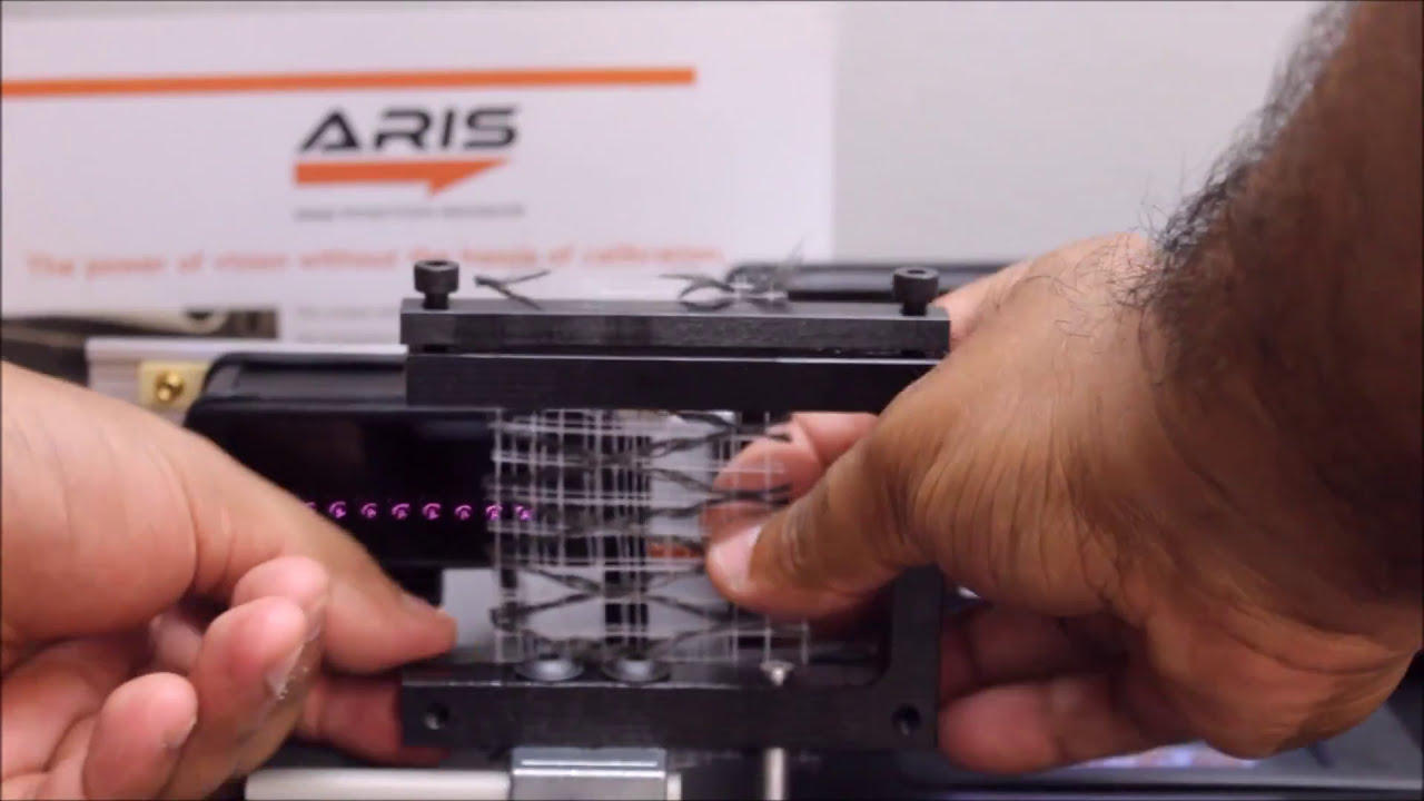
This demo video shows the capabilities of the Roll-2-Roll Technologies web position sensor to work with different web materials without the need for any setup or calibration.

Web width measurement with ARIS web position sensor from Roll-2-Roll Technologies is shown in this video. The capabilities of the sensor include both web width measurement and monitoring.
Transcript
Show full transcript (293 words)
Roll-2-Roll Technologies adds width measurement to its ARIS line of products. Absolute or relative web width can be measured based on the sensor configuration. With two output options the user has the flexibility to monitor the width based on their need. The real-time measurement can be output as an analog voltage between 0 to 10 Volts.
As the width changes the analog output increases or decreases proportionally. In this video absolute web width is measured using ARIS WPS 221 a 221 mm wide sensor. A 7 volt output corresponds to 70% width coverage which is equal to approximately 6 inches. The analog width measurement option can be used for quality monitoring and real-time control of web width in extrusion processes.
For low modulus webs, the width measurement can also be used to monitor necking in the web. The digital output option allows the user to set pass/fail conditions based on web width. A low and a high limit for width tolerance can be set. The resolution of the tolerance is in millimeters.
If the actual measurement is within the negative and positive width tolerance the voltage will be zero; this corresponds to a pass condition. If the width goes below the lower limit the output will be a negative voltage. A non-zero voltage is a fail condition. Similarly if the with goes above the upper limit the output is a positive voltage.
This pass/fail condition can be used for a variety of quality control purposes. For wider webs two sensors can be used for relative width monitoring. In that case the analog output corresponds to the percentage of web covering the two sensors. The absolute width of the web can be obtained based on the physical distance between the two sensors.
For more information please contact us.
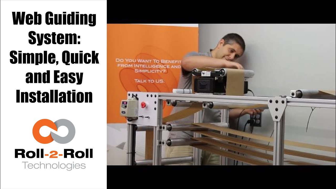
This video shows how easy it is to install the Roll-2-Roll Technologies Compact Web Guiding System. The complete installation and commissioning can be done within seven minutes.
Transcript
Show full transcript (366 words)
In this video we show how quick and easy it is to install an ARIS Web Guiding System. Unpack the box and lay down all the components such as the cables, web guide mechanism, the web position sensor and power supply. The compact web guiding system is pre-wired for easy installation. All that is required is a single allen wrench tool to fasten the web guide to your machine frame using the mounting holes at the bottom of the web guide.
We even provide the 6 millimeter mounting screws with spacers to make it really quick and easy for you. Carefully unscrew the four mounting screws and spacers from the web guide. Place the four spacers over the pre-drilled mounting plate on your machine. Carefully set the web guide over the spacers paying attention to the direction of travel of the web.
Use an allen wrench to securely mount the web guide onto your machine frame. The compact and lightweight design of our web guiding system makes it easier for quick installation on your machine. The mounting holes also provide the necessary electrical grounding of the web guiding system if the machine frame is properly grounded. Please refer to our user manual for more information about grounding.
Next mount the web position sensor on the aluminum rails already mounted on the web guide. Use the thumbscrews to secure the sensor to a desired position. Using the 12 pin DIN connector on the sensor cable, connect the sensor to the web guiding system Make sure to thread the sensor connector all the way through to secure it in place. Next connect the power to the web guiding system using a pre configured power supply.
Once the web guide powers ON set it to automatic control and the web guide is ready for operation. NO other setup or calibration is required. The intelligent control system takes care of the rest of the settings for the sensor and the controller. We have spent the time on R&D so that you save every minute of your valuable time.
That’s how quick and easy it is to install our guide. All in less than 7 minutes. For more information please contact us.
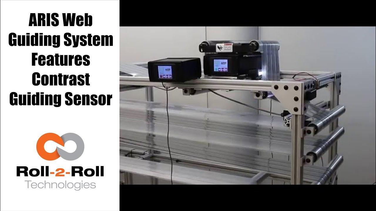
Roll-2-Roll Technologies compact web guiding system can be used for contrast guiding with the ARIS Web Position Sensor as shown in this video.
Transcript
Show full transcript (297 words)
our web guiding system ARIS features the latest in web guiding technology it adapts to any material, requires no calibration and is very simple to setup. Now it features a comprehensive guiding sensor that can be used in any kind of sensing including edge, line, contrast, composite or layered web detection. In this video we use two web guides as a test machine to introduce several speeds and disturbance frequencies. One web guide creates a disturbance while the other correct this disturbance.
This test allows us to evaluate how our machine adjust to these different disturbances. This video shows contrast guiding of composite web where the web is guided based on a die cut of the label. Our web guides can work with continuous or intermittent lines or contrasted edge. Our edge sensor detects the web position of any materials used without the need for manual adjustments.
A previous version of our sensor used a reflection of infrared light to take a picture of the edge of the material. These pictures and processed using digital signal processing algorithms to accurately sense the true position of the material irrespective of its physical properties. The updated version is more comprehensive and uses white light to take a picture of the web materials and in the line detection mode, the sensor can handle a solid or intermittent line or even in contrast between two materials. As you can see this video, the web guide is unaffected by missing labels.
Our tests have shown our sensor technology works automatically with materials of varying contrast. The use of fiber-optic technology eliminates a need for focusing and eliminates need for calibration and set-up. There are details on these experiments available in our white papers. You can find a link in our description below.
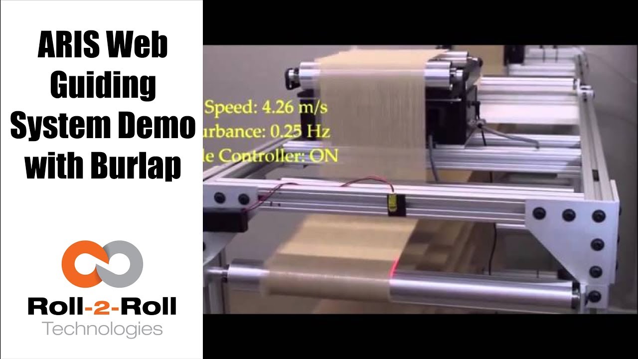
The performance of the compact web guiding system with a challenging porous web, burlap web is shown in this video.
Transcript
Show full transcript (125 words)
The video shows ARIS guiding a burlap web at different frequencies and a web speed of 4.26 meter per second. Using a two guide test machine, we will show you several speeds and several disturbance frequencies that are introduced to evaluate the performance of ARIS when it handles burlap, a non-porous material. Watch the red laser to see difference of the controller when its on vs when its off. As a porous material, burlap presents a special challenge because current sensing technology is not able to handle the gaps between the threads of the material.
The image processing in the sensing technology in ARIS allows it to detect the edges of a porous material. You can find a link for more information in our description below

Roll-2-Roll Technologies web guiding system uses a revolutionary fiber optic web sensing technology to accurately measure web position. In this video, several speeds and several disturbance frequencies are introduced to evaluate the performance of the web guide for a sinusoidal disturbance commonly seen in web lines.
Transcript
Show full transcript (106 words)
ARIS is an intelligent guiding system that uses a revolutionary fiber optic sensing technology to accurately measure web position. In this video, we use a two guide test machine to introduce several speeds and disturbance frequencies. One machine creates the disturbance, while one corrects this disturbance This test lets us evaluate how our machine adjusts to these disturbances. Watch the red laser to difference between when the controller is off vs when it’s on.
We have a white paper on our website that gives more information about the performance of our guide systems. For more information, please click on the link below in our description.