Controller Installation
-
24 VDC power supply with a minimum of 5 Amps is supplied by Roll-2-Roll Technologies or available from customer.
Suggested power supplies: Mean Well SDR-120-24 or SDR-240-24 -
24 VDC power supply cable with connector is supplied by Roll-2-Roll Technologies or available from customer.
Suggested alternative to factory supplied cable: Switchcraft CA761KS07984 or CARA761KS07984
-
Length of the power cable is sufficient to connect the power supply in the cabinet to the SCU5 controller/operator interface installed at a desired location for operation.
-
The SCU5 controller case is grounded to the protective earth or the earthed ground. The mounting holes or the mounting brackets are used to make proper protective earth connection.
-
The red wire is connected to +V (+24 VDC) and black wire is connected to -V (GND) on the DC side of the power supply. The red and black wires are for the cables supplied by Roll-2-Roll Technologies.
-
When the power supply is connected to the SCU5 controller, the operator interface powers up and the communication indicator or the heartbeat is blinking on the controller screen.
Sensor Installation
-
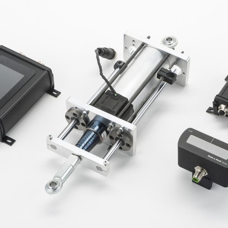
The sensor mounting rail is supplied with the sensor or is available: Low Profile Sensor Rail or 1” Sensor Mounting Rail
-
The sensor slides freely in the rail and can be locked in a desired position on the rail with a brake or a thumbscrew.
-
The sensor mounting rail is long enough for the desired application, especially when the web width changes.
-
The sensor cable is long enough for the desired sensor location and the SCU5 controller location.
Suggested cable extensions: Turck RKS 12t-5-RSS 12 T or Phoenix Contact SAC-12P-MS/5,0-35T/FS SH SCO
-
The sensor or the sensor cable does not appear to be damaged.
-
After connecting the sensor(s) to the controller and turning ON the power supply, the sensor(s) detect/measure the position of a material in its field of view. The web position is indicated on the operator interface and the web detect LED lights up for the sensor(s).
-
Edge and Center Guiding:
-
For all applications, except contrast guiding application, the infrared sensor is mounted in a free span between two rollers. No object is present within 150 mm or 6 inches from the field of view of the sensor except the web itself. The sensor is within 5 mm to 15 mm (0.2 in to 0.6 in) from the web.
-
For edge or center guiding applications the sensor is installed downstream of the exit roller of the web guide. The sensor is installed within the first one-third or one-half of the exit span. Additionally, the location of the sensor is such that the plane change due to normal guiding action will maintain the web at a distance of 5 mm to 30 mm (0.2 to 1.25 in) from the sensor at all times. An additional backup roller may be installed to reduce the plane change effect.
-
-
Contrast Guiding:
-
For contrast guiding, line guiding and other contrast sensing application, the white light sensor is installed at a distance of 5 mm (0.2 in) from the web. The web in the field of view of the sensor is supported on a backup roller so that the web is stabilized to prevent any plane change or flutter.
-
The sensor and the backup roller are installed downstream of the web guide within the first one-third or one-half of the exit span. The wrap angle of the web on the backup roller is no more than 20 degrees.
-
-
Unwind Guiding:
-
For unwind guiding the sensor is installed downstream of the idler roller that is mounted on the lateral shifting unwind.
-
-
Rewind Guiding:
-
For rewind guiding (or chasing) the sensor is installed upstream of the fixed idler before the rewind. The sensor is mounted on the lateral shifting rewind stand.
-
-
Use the sensor installation recommendation to finalize the location and position of the sensor.
Retrofit Actuator Installation
-
Checking the existing guide structure:
-
The existing guide structure is in good working condition and the roller bearings are good without any movement due to bearing wear.
-
A detailed dimensional sketch or a photograph of the way in which the existing actuator is mounted on the guide structure is recorded.
-
The way in which the actuator connected to the machine frame and the moving guide structure is noted.
-
The existing old actuator is disconnected and all parts are appropriately marked and saved.
-
The guide structure, without the actuator connected, moves freely through its full range of motion without binding.
-
The guide structure can be easily pushed by hand without much effort.
-
If there is any binding the bearing can be cleaned or replaced to prevent any binding.
-
-
Checking the functionality of the new actuator:
-
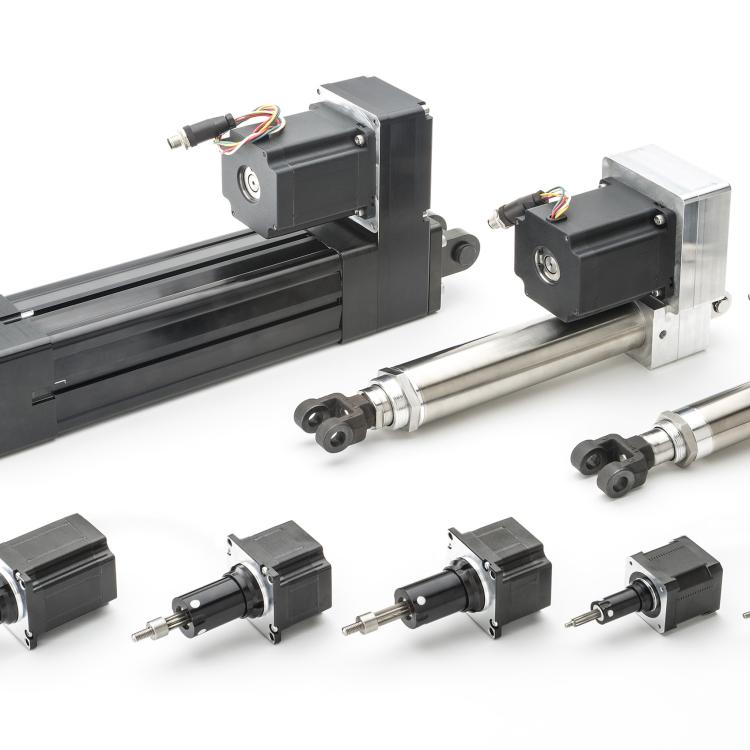
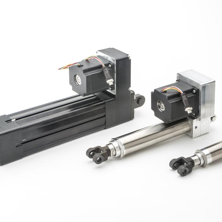
Without installing the new actuator onto the old guide structure the actuator functionality is checked by connecting the communication cable, the actuator cable, and the power cable to the respective ports on the SCU5 controller, the motor driver and the actuator before power is applied.
-
When the Roll-2-Roll 24 VDC power is turned on to the SCU5 controller, the Jog operations on the SCU5 controller moves the actuator back and forth.
-
-
Installing the actuator with fixed mounting option:
-
If the old actuator has fixed mounting options (bolted directly to the machine frame), a new mounting plate is available to appropriately mount the new actuator from Roll-2-Roll to the machine frame.
-
The new actuator is mounted so that the linear motion of the actuator is exactly inline and aligned with the motion of the moving carriage on the existing guide structure rails.
-
The front end of the Roll-2-Roll actuator is mounted to the moving frame with threaded screws or bolts or with pivot pins similar to the old actuator. If pivot pin is used then the orientation of the pin with respect to the stroke of the actuator in the new installation is same as the old actuator installation. If the actuator is directly screwed then thread lockers are used to prevent rotation of the leadscrew.
-
-
Installing the actuator floating mounting option:
-
If the old actuator has a floating mounting option such as a rear clevis or a rear pivot or a rear spherical rod eye, the new actuator from Roll-2-Roll has the same or similar option.
-
The front end of the Roll-2-Roll actuator is mounted to the moving frame with a front clevis rod end or a spherical rod end. The pivot pin is orientated in the same direction as the old actuator installation.
-
The rear end of the Roll-2-Roll actuator is mounted to the machine frame with a rear clevis or a rear pivot eye or a rear rod eye with the pivot pin in the same orientation as the old actuator installation.
-
If the actuators do not have an anti-rotation provision on the actuator, then an anti-rotation mounting is installed during the installation, especially with spherical front and rear rod eyes.
-
The extension and retraction of the actuator allows the actuator to rotate on the front and rear pins for automatic alignment.
-
-
Checking the actuator installation:
-
After reconnecting the actuator cable to motor driver and turning ON the SCU5 controller, the guide structure moves when jogged. The actuator does not struggle to move the guide structure.
-
The actuator is mounted such that the fully retracted and fully extended position of the actuator coincides with the extreme positions of the moving frame on the guide structure.
-
If the actuator stroke is more than the stroke available on the guide structure, the digital stroke length of the actuator is reduced to match the physical stroke available on the guide structure.
-
If the actuator stroke is less than the stroke length available on the guide structure, appropriate mechanical stops are installed to match the actuator stroke length.
-
The actuator is installed so that the center of stroke of the actuator and the center of stroke of the linear raceway match.
-
-
Installing the servo center sensor:
-
If a servo center sensor is installed on the actuator then the position of the servo center sensor is moved such that the guide structure is in the middle of its stroke.
-
The servo center sensor is installed directly on the guide structure then the sensor is installed such that it sees a metal surface (within 2 mm from the servo center sensor) for one half of the stroke and free space for the other half of the stroke.
-
Jogging the actuator back and forth lights ON and OFF the LED on the servo center sensor. The transition between ON and OFF occurs at the middle stroke position of the guide structure.
-
-
Checking the retrofit installation:
-
The Jog functionality on the SCU5 controller moves the guide structure back and forth.
-
The servo center functionality on the SCU5 controller centers the guide structure at the middle position of the guide structure.
-
With the sensor connected to the SCU5 controller, the automatic functionality moves the actuator based on the web position.
-
The actuator polarity is set such that the web guide moves to position the web to the guide point on the sensor. If not the actuator polarity is reversed.
-


