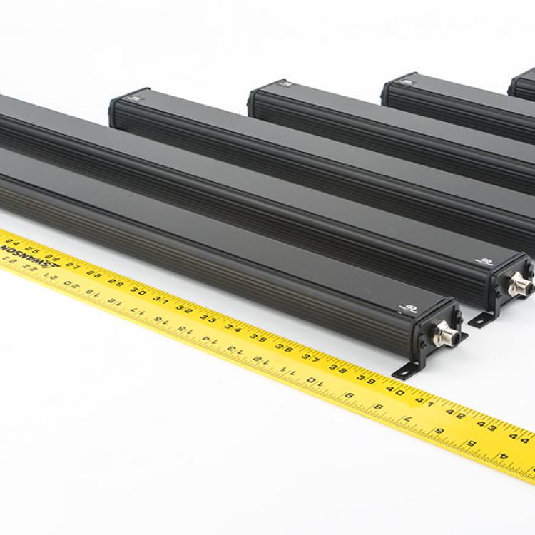
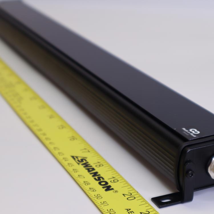
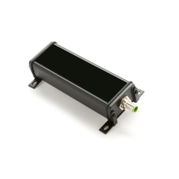
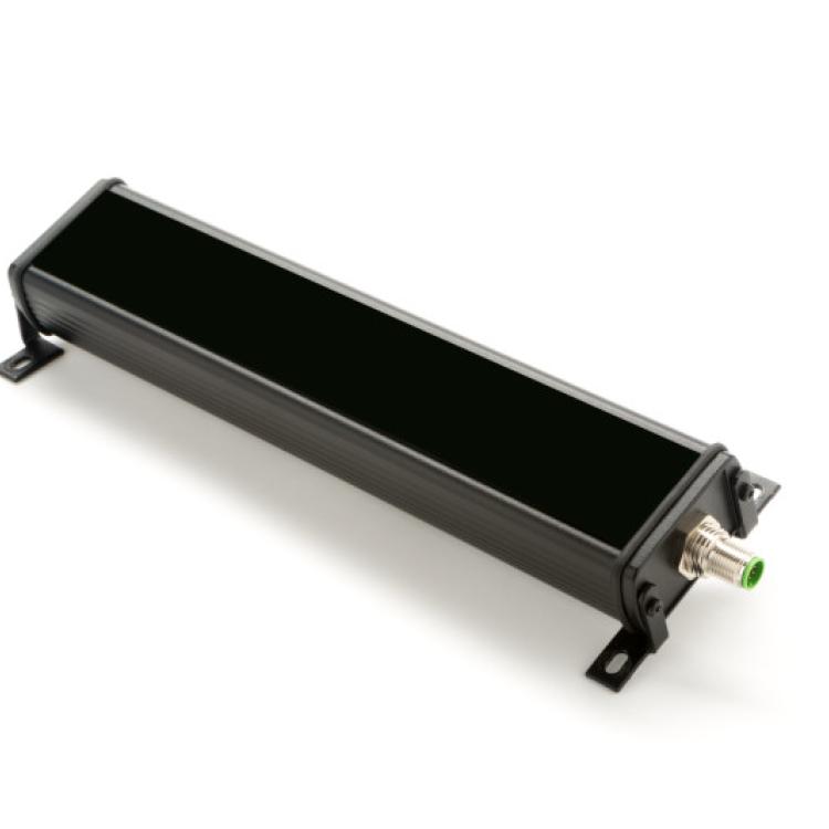
One of the key steps involved in a web inspection application is proper sensor installation. This document outlines a few key recommendations with regard to position and orientation of the sensor for web width and coating width inspection applications.
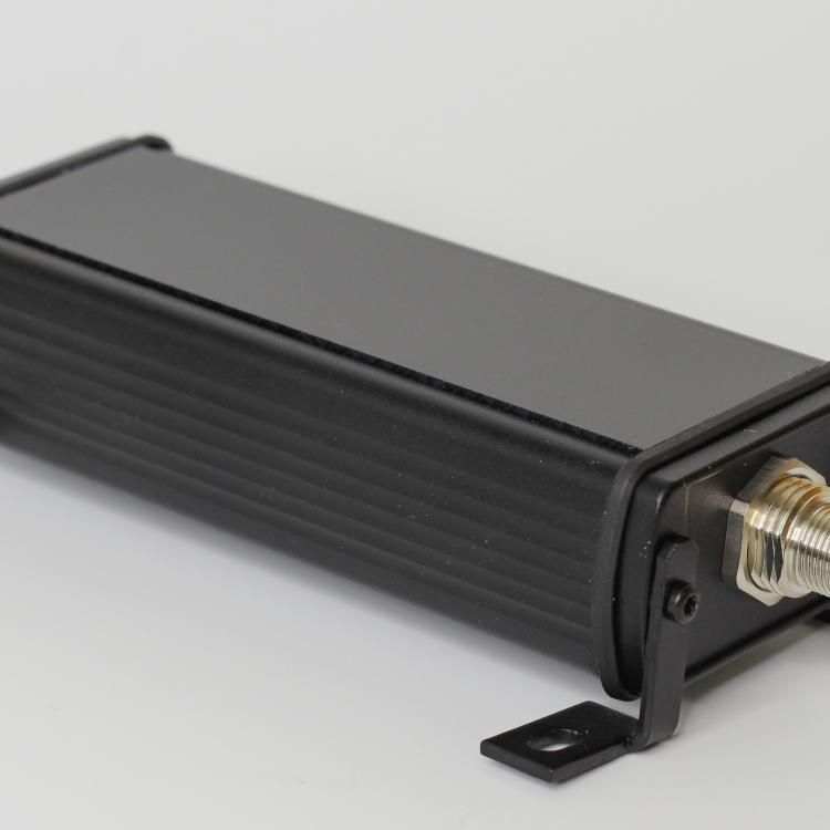
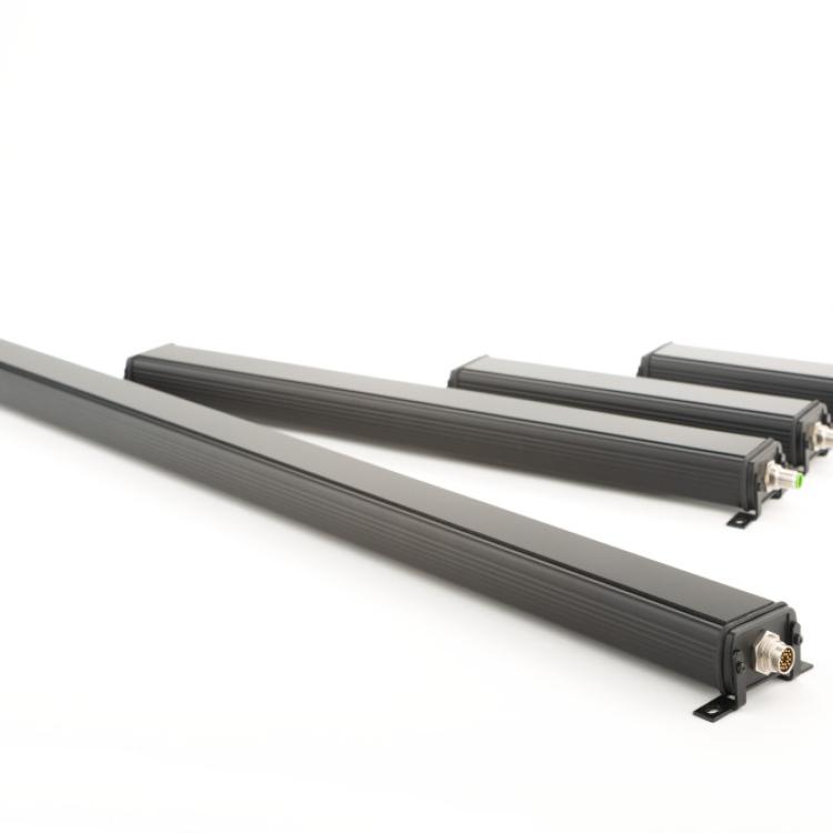
Roll-2-Roll® Sensors are camera based systems that work on the principle of light scattering. Hence the sensor performance is improved with proper installation that can increase light scattering while providing a good image.
Sensor Working Distance and Background
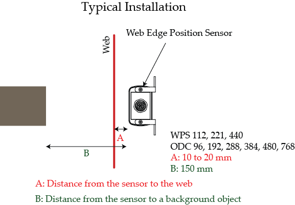
Typically the sensor for web inspection is mounted in a free span between two rollers. The distance of the sensor from the web directly affects the amount of light scattered back from the web. Closer the web is to the sensor, more light will be scattered back from the web. The ideal recommendation for the distance between the sensor and the web is 5 mm to 20 mm depending on the sensor. Note that the sensor would still provide measurement even if the web is farther than the recommended distance for certain applications, however for inspection applications, the recommended distance is between 10 mm and 20 mm.
Since the sensor is similar to a camera, objects behind the web in the field of view of the sensor may be picked up by the sensor. It is recommended that no object (or any other web path) be at a distance of 150 mm from the sensor to increase the performance of the sensor. These recommendations are illustrated as shown below.
For web inspection applications it is important to stabilize the web and remove any out-of-plane vibrations (variation in distance A as the web is transported). The out of plane vibrations can cause the web to be closer and farther away from the sensor creating varying amounts of back scatter. This affects the quality of the image captured and also creates artificial contrast variations that change as the web moves closer and farther away from the sensor. One of the simplest ways to stabilize the web is to install the sensor between two fixed idle rollers as shown here.
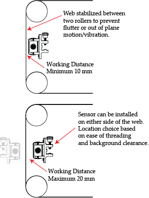
The sensor may be installed on either side of the web. The choice depends on the ease of web threading as well as the available free space behind the web in the sensor’s field of view.
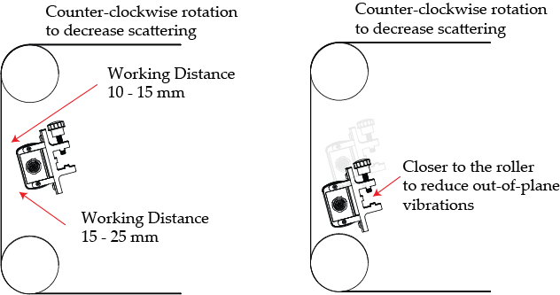
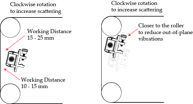
Additionally, installing the sensor closer to one of the rollers will also help with reducing the out of plane motion. Ensure that if and when the sensor is installed close to an idle roller, the background free space condition is met.
In the event of tight installation, a black matte artificial background can be used to overcome the requirement for the clear space behind the sensor. The black matte background will absorb the light from the sensor and prevent it from reflecting back into the sensor. It is important that the material is matte and black in color to ensure 100% absorption of the light from the sensor.
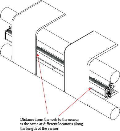
It is also important to ensure that the entire face of the sensor is at a constant distance from the web along the entire length of the sensor. This is necessary to have an uniform image intensity along the length of the entire sensor range.
Sensor Orientation to Maximize or Minimize Scattering for Inspection Applications
Some webs reflect more light than the amount they scatter. For example, metallic, shiny/glossy and clear webs can reflect most of the incident light away from the sensor and scatter only a tiny fraction of the light. Since for reflective webs, the angle of incident of light is the same as the angle of reflection, proper angular orientation of the sensor with respect to the web would significantly improve the amount of light coupled back into the sensor. Since the LED light source inside the sensor is at an angle, the sensor can be tilted as shown below to increase scattering.
Sensor Orientation to Maximize Scattering for WPS 112, 221, 440, ODC 96, 192, 288, 384, 480, 768
To maximize the scattering they need to be installed so that the LEDs inside are normal to the web. This can be achieved by installing the sensors as shown below. Note that the clockwise rotation is viewed from the end where the sensor connector is visible.
Sensor Orientation to Minimize Scattering for WPS 112, 221, 440, ODC 96, 192, 288, 384, 480, 768
The rotation of the sensor in the counterclockwise direction will result in reduction of scattering. This may be needed for certain applications to increase the contrast between two different surfaces. Especially in Lithium-Ion battery inspection applications it may be necessary to reduce the scattering to increase the contrast difference between the coated and uncoated web. This can be achieved by the orientation shown below.
