Unveiling the Advantages of the SCU6x Controller & ODC Sensors
Transcript
Show full transcript (296 words)
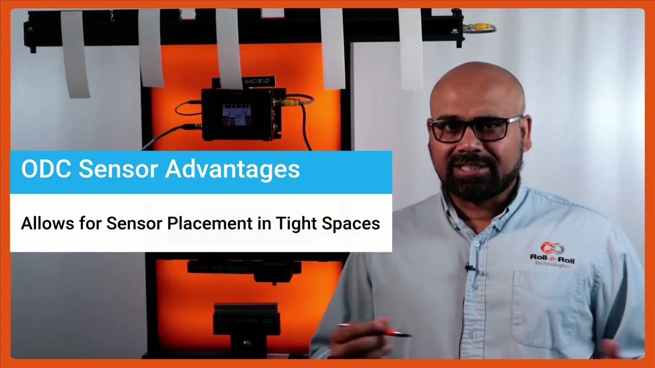
One of the key things with our SC6X controller and the ODC sensors is that [music] they not only are used for guiding purposes, they're also used for any type of cross machine direction width measurement applications. It could be measuring the width of a single web or multiple webs. Here again to reiterate on some of the advantages of the ODC sensor is that it's a one-sided sensor technology. So it allows us to install the sensor in tight installation spaces whereas a camerabased traditional machine v machine system might need a long longer field of view and working distance which creates issues if you want to add an width measurement system to an existing machine.
The other advantage is that the light source, the optics and the camera, everything is built into a single interface like what we have here. We don't have to have a separate light source or gantry [music] to have the camera and the light source built in. The third advantage is that the sensor provides a one one magnification. If the object is 100 mm wide, we're using a sensor that is at least 100 mm wide.
So, we get a one one magnification. The advantage is that when you go to a wider width, you don't lose any resolution. So for example, this ODC 960 which is a measuring range of 960 mm can provide the resolution of 127 micron on the camera level and then sub pixel with that you could get up to about 33 micron resolution. your resolution is not affected by the field of view that you are requiring.
Because of these advantages, the ODC sensor is used for a lot of different applications, especially in existing slitter rewinders where you want to measure the width of the material.
In this episode of the Multiple Web Width Measurement Application Series, we showcase the advanced pattern teaching feature of the SCU6x controller. Learn how to set up widths, samples, and jobs to monitor changes in material movement and width accurately. Discover the advantages of the pattern teaching mode, such as alerting when a web breaks and maintaining precise measurements even with intervening materials.
Transcript
Show full transcript (485 words)
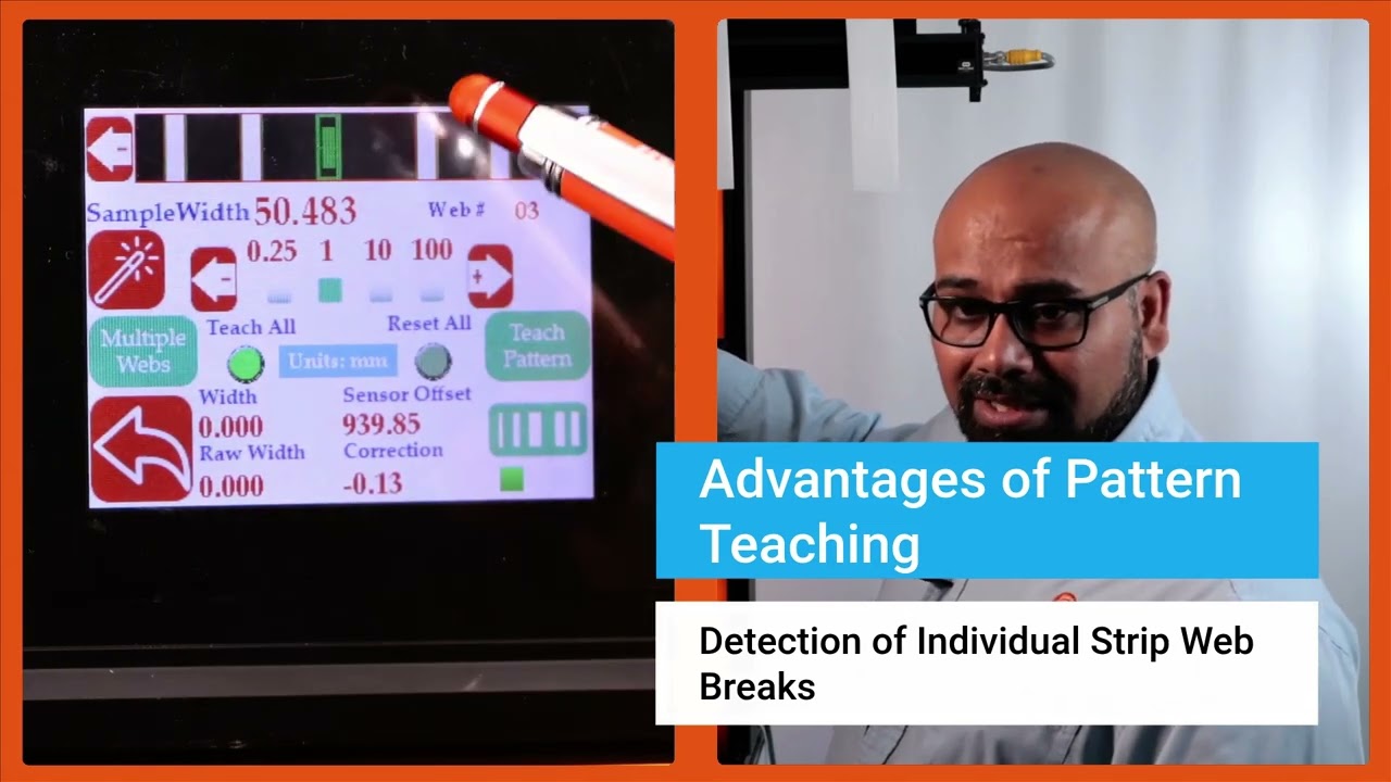
Now we do have another feature that allows you to get even higher um uh uh insight into your process and what that is what we call pattern teaching. So essentially what we will do with the pattern teaching is that we set the widths, we set the samples, we set the job. We're looking for not only the change in the width but also change in the movement of the material. You can enable that by pressing this button that's in the pattern teaching mode.
When you're ready to teach the pattern, we're going to press this teach pattern and press accept. So now the system is taught the pattern. What is the advantage of that? If I have uh let's say I'm in web 3, right?
And if the web three breaks right now, it is actually showing you that hey, I'm supposed to see a web there. It's broken. The value is zero. And it's going to provide an alarm or alert right there.
That's one advantage of that. Another advantage with that is that let's say I have a web five that I'm tracking right here and if I have another material that comes in between there, the web five's measurement is not affected by that whatsoever. In a typical camerabased system, they're going to keep track of the width randomly based on which one is first and which one is second. That would affect the measurement.
If I do have this pattern off, web five will actually jump. You saw that it jumped to that 10 mm and it jumps back. To avoid this jump, we are going to use the pattern. And once the job is set up in your slitter rewinder, it's not going to change.
The pattern is not going to change. Then even if something comes in, that gets completely disregarded. That's the advantage with the pattern teaching or pattern matching mode. Those are the key things with regard to how you can set up our SCS 6x controller for multiple slit width measurement.
Okay, one of the thing that we wanted to show is that this width measurement right now we are in pattern mode. So even in pattern mode, if the web moves back and forth, you can see that the web is moving, but it's also keeping track of that edge position, keeping track of that width pretty accurately. And we can actually move this quite a ways off and that's when it will say that the pattern is supposed to be there, but it has moved from its intended position. So this is an example where let's say the slitter blade moves too much then you can catch that.
Obviously it'll show up in the width but it'll also show up in the web position. As soon as we come back into that location, the actual location itself, then it locks in on that

Setting Nominal Width, Upper and Lower Limits for Multiple Web Width Measurement
Transcript
Show full transcript (798 words)
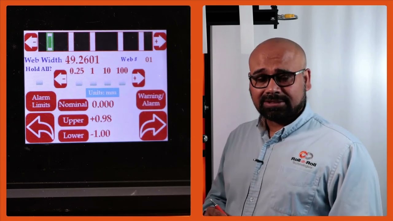
Then like I mentioned for each web we can set an nominal width, upper limit and lower limit. Right now I'm going to show you how we can set those things. So in order to set the nominal width we're going to press that nominal width icon and then we're going to choose how much increment we want to make. So I'm going to do 10 mm increments here.
So I'm going to change that to 50 mm. Okay. So the nominal width is 49.24. That's it.
There's no need to save anything here. Anytime you change that, that parameter is automatically saved and saved into the memory. So when you power cycle it, it comes back in. Likewise, you can set the upper limit and the lower limit.
So you choose the parameter that you want to change and pick the increment. If I do 1 mm increment that's going to be like that and you can do it like that. It's very simple intuitive way to change it. And likewise you can change those things too.
Now there are applications where we would have two types of outputs. One is to say that if my width is above a certain upper limit or if the width is below a certain lower limit you want to trigger an output there. So in those cases we would have something what we call as that upper limit lower limit kind of thing. So this is a pretty simple setting.
All that we are looking for is hey if the width goes above my upper limit trigger an output or if the width goes below the lower limit trigger another output. So just two boundaries and then within the nominal range the output is not triggered all good signals are provided. If you want an additional layer where you want to set alarm limits and warning limits then we can do that too. So in this particular case then you need to make sure that it is in alarm and warning.
When you have this in alarm and warning you have this button show up just to show you one one more time. If I have it just on upper and lower limit these are the two parameters we can enter. But if we are in warning and alarm there are four parameters you can enter. The first two parameters are here and the second two parameters are warning limits.
warning signal so that you don't have to stop the machine when the warning signal is there. This is just for the operators to know something is getting to get bad and once it hits the alarm limits then you can stop the machine if you wanted to. Just like I mentioned the warning limits are going to be closer to your nominal width and the alarms are typically farther away from there. So in this case we have it set as plus or minus.5 mm and then this is plus or minus.1 mm for that and you can do that for every single web.
You can set the upper limit, lower limit, alarm and warning limits. Right now for web two it's not set up. Web three you can see what is set up there. None of these are set up there.
But that's the way for us to set this up for the alarm and warning so that when the width changes you have the ability to provide a digital output to a stack light or something like that. So that is essentially how to set the multiple width measurement these warnings and alarms. And again just to go through this one more time I'm going to pick width two. I'm going to set that nominal width to be 49 point let's say.5 there.
So I am in warning and alarm. So I'm setting the alarm limits for this. So I'm going to set this as 1 mm and the lower one as 1 mm as well. And alarm I'm going to set this as 0.5 and 0 five for that.
And then you can keep doing that for multiple webs. And if you go back here, you can see for the different values, different webs, you see different values there. When I go from one to another, you got all of these set there. All of these are saved in the memory.
Then you have that option to do it. This is where you use the controller. An operator is manually setting this. All of this can be automated through Ethernet and you can send a recipe to our controller to say web one should be this width.
The upper limit is this and the lower limit is this. Upper warning limit is this and lower warning limit is this and so on and so forth.
In this episode of our webinar series on web guiding fundamentals, we explore the installation and operational intricacies of a steering guide. We cover the mechanics of a single roller installed on angled raceways, its bending action, and essential guidelines for entry and exit spans. We discuss the importance of maintaining a 90-degree exit span angle to minimize stress and prevent issues such as wrinkles and web tear.
Transcript
Show full transcript (631 words)
[Music] The second choice for us would be a steering guide. In terms of how it works, it's a little bit different. You got a single roller. This is the top view and this is the side view.
This roller is installed on two raceways at an angle. The web guide forms an arc like that. It moves and forms an arc back and forth. That's how we are changing the axis of rotation.
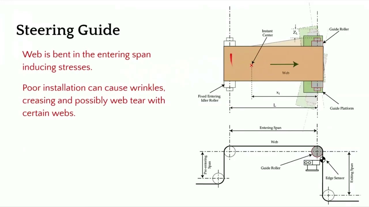
In this web guide, we are creating a bending. So there is a bending action here. It's displacing as well as bending. In terms of the entry and the exit span, there are some guidelines for that as well and we'll go through that.
This is not an ideal choice for us because it's bending. So it's introducing stress. If it's not installed properly, it can cause wrinkles, creasing, web tear, and edge stresses. In terms of installation, what do we need to look for?
We need to make sure that the exit span is perpendicular to the plane of motion of the web guide. The main thing is to make sure that the exit span is in pure twist. This allows us to have the least amount of stress in the web. So we want to do that.
Now the entry and exit span length is also depending upon the stiffness of the web. You typically need a longer entry span for a rewind guide because the motion of the web guide or the displacement of the web happens because of bending. So you have to follow those guidelines in terms of if you have a stiffer web, you need to have a longer span so that you can allow the bending to happen. Normally it's about 1 to five times the width of the web.
And then the exit span can be half a web width. And there's also minimum formula for finding out the minimum span length. In terms of other things here, let me talk a little bit about the instance center. Like I mentioned, there is a raceway, two raceways here, and they are angled so that you can have the web guide go around an arc.
And the center of the arc is called the instant center. This is important. We need to make sure that the instant center is within this span. and it's at a certain distance about half the length of the span or up to 2/3 the length of the span.
These are all numbers coming from the dynamic model of the web guide and the dynamics of the web itself. If you don't follow those conditions, then you can have a web guide over steering, under steering, creating an awful lot of stresses, maybe wrinkles, slack edges, tight edges and all those kind of things. The main things that we want to look for is this angle. Make sure that it's 90° and then you have an entry span that is pretty long.
You can have different wrap here. We don't want to go more than 45° on either side. When you do that, you're adding twisting. Uh so whenever it goes away from this 90°, it's not pure bending.
There is bending and twisting in mold there. And then we want to have an angle here because when you put bending stresses here, you have the possibility of what we call as moment transfer. So the motion of this roller can actually move the web upstream of the guide roller. In order to avoid that, we want to have certain conditions here.
And we also want this span shorter so that it becomes harder for that moment transfer to occur. Those are some of the guidelines for installation of a steering guide and again sensor as close as possible. [Music]
Accessing the operator width measurement and monitoring screen from the home screen is a simple task to perform. In this brief video, we guide you through the steps necessary to set your SCU6x Controller for web width measurement and monitoring. Start by pressing the tools icon, followed by the operator icon located at the top right, and then the width icon. You'll first arrive at the operator width home screen, and there's an additional setup screen available where you can perform further setup tasks.
00:00 Accessing the Operator Width Screen
Transcript
Show full transcript (57 words)
To get to the operator width screen from the home screen, we're going to press the tools icon, then the operator icon on the top right and then the width icon. This first page is the operator width home screen. The second page is an additional setup screen where you're able to do more setup related things.
In this demonstration, we showcase the flag detection capabilities of Roll-2-Roll Technologies' SCU6x Controllers combined with ODC Sensors. The setup includes both unwinding and rewinding mechanisms, with a sensor monitoring the edges of the web. The SCU6x Controller is configured to detect flags effectively, ensuring accurate monitoring even with web oscillation. The video highlights the ease of setting up the system, the parameters involved, and the robust nature of the algorithm, making it a reliable solution for web handling applications.
Transcript
Show full transcript (1186 words)
So what we have set up here in this um demo test setup is um we have an unwind and a rewind. We have added some um flags. Uh there are some flags on the left edge. There are some flags on the right hedge, right edge of the web.
We have a single sensor right here that is looking at the web. And then we do have an SEU6X controller that is set up uh for this flag detection application. So this is the same controller that we looked at in u previous videos. Um I'm going to just quickly walk through how we can set this up for flag detection.
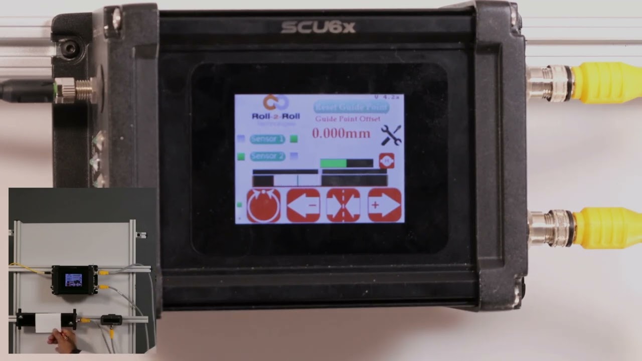
As you can see, we have the um uh sensor one connected. So and it's been set up to center mode because we have a wide enough sensor that can see both edges of the web. And uh um in order to do the flag detection, we're going to go into the tools icon operator on the top right and then the flag detection. So this is the screen where if you are using this just for flag detection applications, then you can be on this screen and monitor it.
But you can set this up, an operator can set this up and you don't have to be on this screen for the flag detection to work. So there are a few things here. Uh just like the home screen, you see a realtime uh preview of where the image is. And since our sensor is looking at both edges of the web, you also see the center line position right there.
Um and then when the flag detection is running, let's say there is a flag, then this flag detect signal would come in. So just to illustrate that, I'm going to artificially create a flag right there. And you can see that the flag detection signal lights on. uh the the duration for which the flag detection is on is called the hold period.
So you can set up all of these. So I'll go in and show you how we can set that up. If you hit the tools icon there, then it's going to bring into this screen. And this is basically where we define certain things.
So what is the minimum length of the flag? Uh when we say length, it's basically how much um uh in distance is it protruding from the edge of the web. So this is in the cross machine direction length. That's what we are talking about.
So if the edge position is in a certain location, how much more is the minimum flag length? Right now we have set it up to 5 mm which is pretty small. Uh depending upon what your application is. Typically for our customers uh it's anywhere from 25 mm which is an inch all the way up to 2 in.
Um but you can set up whatever length you want. And this just means that if the web moves suddenly within this length um or this uh length in the w um cross dimension, it will not trigger a flag. So um the reset duration is basically uh allowing the uh the controller to automatically adapt to wid changes. So if you have a machine running and then you do a on the-fly wid change then instead of um you coming back here and saying hey the new web position is this new location because the width changed uh you can actually set up a reset time.
Essentially that means that for this amount of time if that web position is in this new location we're going to say that that's the new web location. So typically you can set it up anywhere from 5 to 10 seconds. So we'll set it up at 5 seconds. And then hold output.
This is um essentially for um you to take the signal into your PLC. Uh whenever a flag is detected, we output a signal. How long do you want to keep that signal on? That's essentially the hold output duration.
So we will typically set it to 1 or 2 seconds. This really depends upon your PLC and uh if you have a high speed data acquisition system or not. Uh but if you increase the whole time, it just means that uh you guarantee that your PLC is fast enough to see that. So that's essentially it.
That's all the parameters that we have for this. And um if we are now running the machine um we would see that it will start picking up the flag. As you can see there's a flag coming up right now. As the flag goes through um the stack light gets triggered and the stack light is on for the duration that you set so that your PLC can miss it.
So this flag right now that went through was just on the left edge. Here's now on the right edge. You can see that it's picking that up. Just to show you how that works on the controller screen.
Um you have this same kind of an output. When the uh flag comes through, it gets triggered. And um when there's no flag, it's out. And then when the flag comes through, it gets triggered.
You don't necessarily have to be on this screen. Like I mentioned, you can be on a different screen. And this will still trigger the output because that's running in the background. Uh that's essentially it uh in terms of uh uh flag detection.
So just to give you an idea about how robust this algorithm is, we can even set it up to oscillate the web and it will disregard the oscillation and still detect the flag. So I'm going to do that. So now the web is oscillating back and forth. As you can see it's moving.
The flag detection is not getting triggered. When the flag comes through it gets triggered. As simple as that you can have flutter. You can see that the web plane changes quite a bit.
Even then the flag doesn't get triggered. Only when a flag comes through the stack light gets triggered. So just a pretty robust way to detect a flag. Um and you can see that um whether it's left edge, right edge, the sensor automatically knows which edge it is and it detects the flag and provides an output.
So again, Roll to Roll Technologies, we are here to provide you with solutions that are simple to use, robust. Uh we do the research so that you don't have to spend time on trying to um make the machine run just like how you want it to run. uh we do all the heavy lifting so that it's even an operator can set this up and it it doesn't take that much time for you to get this up and running. Um hope you like this video.
If so, make sure to uh like and subscribe to our channel and uh stay tuned for more videos. Thank you.
Multiple width measurement is an application that many operations in converting would like to have. Much better if the application was capable of simultaneously measuring and monitoring the widths of several webs. Join Aravind Seshadri from Roll-2-Roll Technologies as he delves into the capabilities of the SCU6X controller and ODC sensors for web width measurement. Learn about the unique advantages of one-sided sensor technology, such as ease of installation in tight spaces and high resolution, independent of field of view.
Transcript
Show full transcript (4086 words)
Hello everyone. This is Arvin Shadri from Rollto-roll Technologies. Today we're going to talk about web width measurement with our SCU6X controller. One of the key things with our SCU6X controller and the ODC sensors is that they not only are used for guiding purposes, they're also used for any type of cross machine direction width measurement applications.
It could be measuring the width of a single web or multiple webs. Here again to reiterate on some of the advantages of the ODC sensor is that it's a one-sided sensor technology. So it allows us to install the sensor in tight installation spaces whereas a camerabased traditional machine vision system might need a long longer field of view and working distance which creates issues if you want to add an width measurement system to an existing machine. The other advantage is that the light source, the optics and the camera, everything is built into a single interface like what we have here.
We don't have to have a separate light source or gantry to have the camera and the light source built in. The third advantage is that the sensor provides a one:one magnification. If the object is 100 mm wide, we're using a sensor that is at least 100 mm wide. So, we get a 1 one magnification.
The advantage is that when you go to a wider width, you don't lose any resolution. So for example, this ODC 960 which is a measuring range of 960 mm can provide the resolution of 127 micron on the camera level and then sub pixel with that you could get up to about 33 micron resolution. your resolution is not affected by the field of view that you are requiring. Because of these advantages, the ODC sensor is used for a lot of different applications, especially in existing sliver rewinders where you want to measure the width of the material.
Today, we're going to talk about something that is unique to our solution to measure multiple widths with the same system. The advantage of this is that because it's one-sided, we can have multiple webs ranging from one web all the way up to 32 webs per sensor. So that's what we're going to discuss a little bit. We're going to talk more about how this can be set up in the controller interface and then we'll also look at in another video how you can get the data out and what you can do with the system.
Okay, I've got this controller set up right now the home screen on this. The first and foremost thing that we're going to do with the SEO 6X is basically kind of pick the application. SEO6X is a pretty versatile controller. It can be used for a lot of different applications.
So in this case, I'm going to set it up for width measurement application. Could be a single web width or multiple web width. And once we do that, we can go into the sensor screen. Right now, I have just one sensor connected here, but we can connect multiple sensors.
In another video, we'll talk about how we can have multiple sensors either with a gap between them or an overlap between them so that we can stitch the image of two sensors into a single continuous image. In this video, we're just going to look at how to do this with a single sensor. So, I have this connected to sensor one and then you can see all the samples there. Any setting in this is going to be very similar to what we have done in the past with the SC6X controller in terms of setting the brightness, the contrast and all those things.
We would ask you to refer to the previous videos to learn more about that. In this case, we have a pretty good image already done. So, we'll just go into that operator width screen to take a look at the functionalities and what we can do there. To get to the operator width screen, from the home screen, we're going to press the tools icon, then the operator icon on the top right, and then the width icon.
This first page is the operator width home screen. The second page is an additional setup screen where you're able to do more setup related things. We'll cover both these screens in this video. So in the first screen you can see that it is providing you with a lot of different things.
First it's showing you the width of the web and then the web number. And if you want to go look at the width of the next web, press that icon. It'll go to web two and it's going to show you the width of the web there. And you can keep scrolling through basically how many webs you have.
You can go through these two icons on the top allow you to scroll through the webs. In this case, we are looking at multiple webs. For each web, we can set an upper limit, a lower limit, and a nominal width. The units are in millimeters.
If we change the units to inches, then everything will show up in inches. So, just to show you how this will work in inches. You can go back couple of one screen and then go to the display icon in the operator menu. And then the units, you can change it to inches.
And now the units on this screen will all be on inches. Then like I mentioned for each web, we can set an nominal width, upper limit, and lower limit. Right now I'm going to show you how we can set those things. So in order to set the nominal width, we're going to press that nominal width icon.
And then we're going to choose how much increment we want to make. So I'm going to do 10 mm increments here. So I'm going to change that to 50 mm. Okay.
So the nominal width is 49.24. That's it. There's no need to save anything here. Anytime you change that, that parameter is automatically saved and saved into the memory.
So when you power cycle it, it comes back in. Likewise, you can set the upper limit and the lower limit. So you choose the parameter that you want to change and pick the increment. If I do 1 mm increment that's going to be like that and you can do it like that.
It's very simple intuitive way to change it. And likewise you can change those things too. Now there are applications where we would have two types of outputs. One is to say that if my width is above a certain upper limit or if the width is below a certain lower limit you want to trigger an output there.
So in those cases we would have something what we call as that upper limit lower limit kind of thing. So this is a pretty simple setting. All that we are looking for is hey if the width goes above my upper limit trigger an output or if the width goes below the lower limit trigger another output. So just two boundaries and then within the nominal range the output is not triggered all good signals are provided.
If you want an additional layer where you want to set alarm limits and warning limits then we can do that too. So in this particular case then you need to make sure that it is in alarm and warning. When you have this in alarm and warning you have this button show up. Just to show you one one more time.
If I have it just on upper and lower limit these are the two parameters we can enter. But if we are in warning and alarm there are four parameters you can enter. The first two parameters are here and the second two parameters are warning limits. warning signal so that you don't have to stop the machine when the warning signal is there.
This is just for the operators to know something is getting to get bad and once it hits the alarm limits then you can stop the machine if you wanted to. Just like I mentioned the warning limits are going to be closer to your nominal width and the alarms are typically farther away from there. So in this case we have it set as plus or minus.5 mm and then this is plus or minus.1 mm for that and you can do that for every single web. You can set the upper limit, lower limit, alarm and warning limits.
Right now for web two it's not set up. Web three you can see what is set up there. None of these are set up there. But that's the way for us to set this up for the alarm and warning so that when the width changes you have the ability to provide a digital output to a stack light or something like that.
So that is essentially how to set the multiple width measurement these warnings and alarms. And again just to go through this one more time I'm going to pick width two. I'm going to set that nominal width to be 49 point let's say.5 there. So I am in warning and alarm.
So I'm setting the alarm limits for this. So I'm going to set this as 1 mm and the lower one as 1 mm as well. And alarm I'm going to set this as.5 and 0 five for that. And then you can keep doing that for multiple webs.
And if you go back here, you can see for the different values, different webs, you see different values there. When I go from one to another, you got all of these set there. All of these are saved in the memory. Then you have that option to do it.
This is where you use the controller. An operator is manually setting this. All of this can be automated through Ethernet and you can send a recipe to our controller to say web one should be this width. The upper limit is this and the lower limit is this.
Upper warning limit is this and lower warning limit is this and so on and so forth. So just to reiterate this is the procedure for somebody to set up a job. If you want to have all of these alarm warning limits you can set for individual webs and then set them up. to make it simple.
If you have a recipe or a job number, you can automate this by setting these through Ethernet if you wanted to. One other thing we need to do whenever we are initially setting up is u one-time calibration procedure that can be done on this screen. The idea for this is that we have the ability to calibrate our sensor for your conditions. We do have a calibration done in the factory, but when it's being installed, the sensor might be installed at a different distance than what we typically expect.
And then there are other things with the lighting and contrast that might change some of these parameters. So this calibration is necessary only if you're looking for a higher resolution measurement. For example, if you're looking for a tolerance of plus orus 1/16th of an inch, you don't need to do any of these calibration things. But any anytime you are below that.
So anytime you're below a millimeter or below a 1/16th of an inch resolution, you would need to do a calibration. This is done just for that particular setup. Once you do it, you don't have to do it for the rest of the run. It'll be stored and take that calibration value.
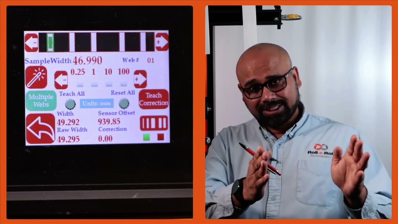
What does the calibration do? Essentially, I have a material or a sample of a known width and the sensor is providing a raw measurement. We're going to compare those two and then say the calibrated measurement is based on the actual sample width and whatever the raw offset is, that's the correction we're going to use for the rest of the measurements. So, that's indicated here.
So that's basically saying what is the correction from the actual width to the measured width. That's essentially what the calibration is. So it's just creating a offset. So for example, let's say the sample width is 46.
To change that, you press whatever you need to increment by and change that value. I am going to put that as 49.244. Right now it's measuring 49.293. If I want to teach this, my sample width should match my measured width.
To do that, press this teach icon and then press accept. Now it has applied a correction. Essentially the raw width plus this correction gives me my actual width. And that's pretty simple.
It's just a regular bias or correction that we are adding. Nothing fancy about this calibration. So you can do that for all these other materials. We don't necessarily need to do this if your tolerance is 1/16th of an inch or 1.5 mm.
We don't need to do that. But for some customers looking for a higher resolution, you do that calibration procedure. Now, just to make it simple, you can enter all of these sample widths already and then you can do a one-time teaching. Let me show you how that works.
I'm going to enter this sample width here. Okay. So, if I want to do all of them together, I'm going to press this teach all button. Make sure that it's highlighted.
And then I'm going to press this teach and accept. Now, all these samples will have a correction. Before we had everything as zero. And if I now scroll through web 5, web 4, web 3, web 2, and web 1, all of them now have a correction.
So it's just a quick way for you to do this. The general use case for this is that let's say you are a customer in automotive or medical and you have a QC process where you are only sampling a part of your product. You're setting up your slitter. You pull the initial sample after the operator has set up the slitter and you take that sample and you're doing a QC on that.
Now essentially what you're going to do is take that sample and enter it like what I have here. Then you're going to do a teach all. Once that is done during any part of the run, we are taking that measurement online in line 100% of the time. So that's the biggest advantage with this system.
In your typical process right now, you might be doing one sample at the beginning of the run. At the end of the run, the operator needs to stop the machine, take that sample, give it to QC, take the measurement, and then everything is good. You run it, and then every time the machine is stopped, there is another sample that is taken. So, this is a random sampling process with a lot of time involved between one run to another.
and we completely eliminate that and allow you to keep running the machine and monitor the width all the time. So that's the biggest value proposition with our system and that's essentially it. So that will allow you to calibrate each of these samples and be done with it. Now we do have another feature that allows you to get even higher insight into your process and what that is what we call pattern teaching.
So essentially what we will do with the pattern teaching is that we set the widths, we set the samples, we set the job, we're looking for not only the change in the width but also change in the movement of the material. You can enable that by pressing this button. That's in the pattern teaching mode. When you're ready to teach the pattern, we're going to press this teach pattern and press accept.
So now the system is taught the pattern. What is the advantage of that? If I have uh let's say I'm in web 3, right? And if the web 3 breaks right now, it is actually showing you that, hey, I'm supposed to see a web there.
It's broken. The value is zero and it's going to provide an alarm or alert right there. That's one advantage of that. Another advantage with that is that let's say I have a web five that I'm tracking right here.
And if I have another material that comes in between there, the web f measurement is not affected by that whatsoever. In a typical camerabased system, they're going to keep track of the width randomly based on which one is first and which one is second. That would affect the measurement. If I do have this pattern off, web 5 will actually jump.
You saw that it jumped to that 10 mm and it jumps back to avoid this jump. We are going to use the pattern and once the job is set up in your slitter rewinder, it's not going to change. The pattern is not going to change. Then even if something comes in that gets completely disregarded.
That's the advantage with the pattern teaching or pattern matching mode. Those are the key things with regard to how you can set up our SCS 6X controller for multiple slit width measurement. Okay, one other thing that we wanted to show is that this width measurement right now we're in pattern mode. So even in pattern mode, if the web moves back and forth, you can see that the web is moving, but it's also keeping track of that edge position, keeping track of that width pretty accurately.
And we can actually move this quite a ways off and that's when it will say that the pattern is supposed to be there, but it has moved from its intended position. So this is an example where let's say the slitter blade moves too much then you can catch that. Obviously it'll show up in the width but it'll also show up in the web position. As soon as we come back into that location the actual location itself then it locks in on that.
For customers that are looking for really high resolution measurement and high accuracy measurement. We also have other features to compensate for the installation of the sensor. In the previous section, I talked about the brightness, the contrast and all those kind of things. But on top of that, if you want to get a really high resolution measurement, then there are a few other things that we can compensate for.
One of the compensation is for how the sensor is aligned with respect to the machine. Obviously, we want the sensor face to be parallel to the surface of the web and we want the sensor to be at a certain distance from the web. But it can be installed at an angle and even small angles make a big difference in the measurement. So the example would be if I have a sample that is straight but if I put it at an angle then I'm looking at the essentially it's basically a cosine kind of thing.
So you are adding more to the width than that. So there is an issue with how the web is presenting. Ideally the camera it's it's just a line but you have two sensors in there. So there are two rows.
So we want the web to be perpendicular to the two rows that we have. Now it's impossible for somebody to install it exactly perpendicular. So we have that compensation available there. So I will show you how we can take care of that.
So when you first install the system and you want to compensate for the angle, the way to do that is that we can go into the power user screen and from there you would be able to set this up. So to get there, click on the tools icon bottom right power user and then go into the sensor. You can see that sensor one and it's identifying as ODC960. This is the number of pixels it has and all those kind of things.
There are actually 10 cameras in there. So for these high resolution measurement when you when we set this controller up on the back of that sensor, we will have a factory calibrated string of 10 numbers that you need to enter. So it will vary between five and 15. For each one of them, it'll be a number.
You can pick that number and whatever that number says you can set that number there by moving the upper and lower numbers. That's the first thing we need to do. The second thing we need to do is compensate for the angle. So that that is another thing that we have in documentation that you can look at and it will tell you what that number means.
There is a small measurement that you need to make when you do the first installation. And once you have that, that number you're going to come in and enter in that last column. These two things are necessary if you're looking for a measurement resolution of sub mm, actually sub 250 micro. Anytime you want that high of a resolution, we need to make sure we have these things set up.
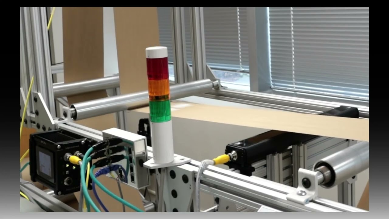
This is a factory calibration number that you need to enter. The slope correction is another number you need to enter in this screen. When we do multiple click width measurement and we have a digital output that triggers an alarm limit or a warning limit, you can tie that to a stack light. If you have multiple web widths, multiple split widths, then if any one of them is out of the range, then those stack light would get triggered.
So we have one output for alarm, one for warning, and one for all good. And if any one of those lanes violate that condition, you will have that digital output get triggered. Just to show you how that works. Um, I don't have a stack light connected, but I do have a signal that would go out when that happens.
And you can see that information on the SCU6X controller. So that's what I'm going to show. In order to get to that screen, press the tools icon on the bottom right and then the arrow key on the bottom right and then digital IO. We want to make sure that the digital output is set for width.
And then you can see a real-time view of what the three outputs are. Right now I've got output three enabled because everything is as per the tolerances. So if I move or change the width of this material, you can see that it it triggers that alarm when that width changes. So if I have something that is narrower, you got that those are the alarm limits and walling warning limits that gets triggered.
So like I said it could be any any lane and that will provide the visual output for the operator to know there is a warning or an alarm doesn't tell you what lane it is. When we get this data through Ethernet then you would have information about exactly which lane has the problem and what kind of an alarm that we have in there. So we'll look at that in the next video. Just to summarize, in this video, we looked at how to set up a single sensor for multiple slit width measurement where you can set it up just directly on the SCU6X controller.
And we also saw how when you connect to a digital stack light, when the width of any of these lanes go above or below the limit, then you have the ability to trigger that stack light. In the next video, we'll look at how we can collect this data through the Ethernet and what are the functionalities that we have through Ethernet. And we'll also look at the app that we have and the app, the data that we can collect from the app and so on and so forth. So, please follow and subscribe to our channel and we'll see you in the next video.

How to Find the IP Address of Your SCU6x Controller
In this tutorial, we'll guide you through the steps to find the IP address, subnet, and gateway of your SCU 6X controller using the tool icon, power user, and communication settings. Discover the type of module you have - in this case, an ethernet IP module - and ensure you're connected to the correct network to connect to the app.
00:00 Introduction to Finding the IP Address
00:14 Understanding the IP Address Details
00:23 Module Type and Network Connection
Transcript
Show full transcript (80 words)
So, in order to find the IP address of the SC6X controller, we're going to go into the tools icon, bottom right, power user, and then communication. It's going to tell us what the IP address of the devices, the subnet, and the gateway. It's also showing us the type of module that we have. This is an Ethernet IP module. So we need to know that IP address and be inside that network to connect to the app.
In this video, we explore the nuances of using different sized sensors for center guiding in web applications with the SCU6x Controller. Normally, it’s recommended to use two sensors with the same measuring range and resolution to avoid confusion. However, this video demonstrates how it's possible to use sensors of varying sizes and addresses the potential confusion that may arise. You'll learn about sensor configuration, including how the screen displays information when different sensors are used, and how the web position indicator operates.
Transcript
Show full transcript (363 words)
one of the things that I want to point out is that in uh normal situations we will always ask that uh when you do Center guiding with two sensors that you use two of the same sensors with the same measuring range and same resolution it just makes it easy and it avoids any confusion here I just wanted to show that it's possible to use different sizes of sensors when you do centering uh what where does this confusion come from just to show on the screen what I mean by that we have one sensor configur to left and the other sensor configur to the right and when we do that the screen is going to be split up into two regions or the web position indicator is going to be split up into two regions if I present the web on just one sensor so I'm presenting it on sensor one which is config as great sensor you can see that only that great half is being updated likewise only the left half is being updated and then when I have a web wide enough it sees both sensors then the portion of the left half corresponding to the left sensor and the portion of the right half corresponding to the right sensor is only going to show up there so the confusion arises mainly because we have one sensor that is almost six times or or eight times wider than this sensor but we only have the same 50% uwing area on the top so when we move just a little bit on the bottom sensor it seems like it's moving a lot whereas when we move little bit on the top the the right left sensor then it seems like it's moving a little but in reality it's moving the same amount but it's just that on the screen we don't have we're not scaling that based on the two different sensors range so that's the difference so we covered the main things with the sensors in terms of the orientation how the web position is indicated how you get the web detect signal and things like that
This video shows how to set the actuator parameters on the SCU5 controller.
Since Roll-2-Roll Technologies offers several different actuators from different vendors, this allows for lot of flexibility for the end customer.
👉🏻 More information on the actuator are here: 🔗https://r2r.tech/products/roll-2-roll-actuators For more information about the SCU5 controller please visit: https://r2r.tech/products/roll-2-roll-controller.
Transcript
Show full transcript (1887 words)
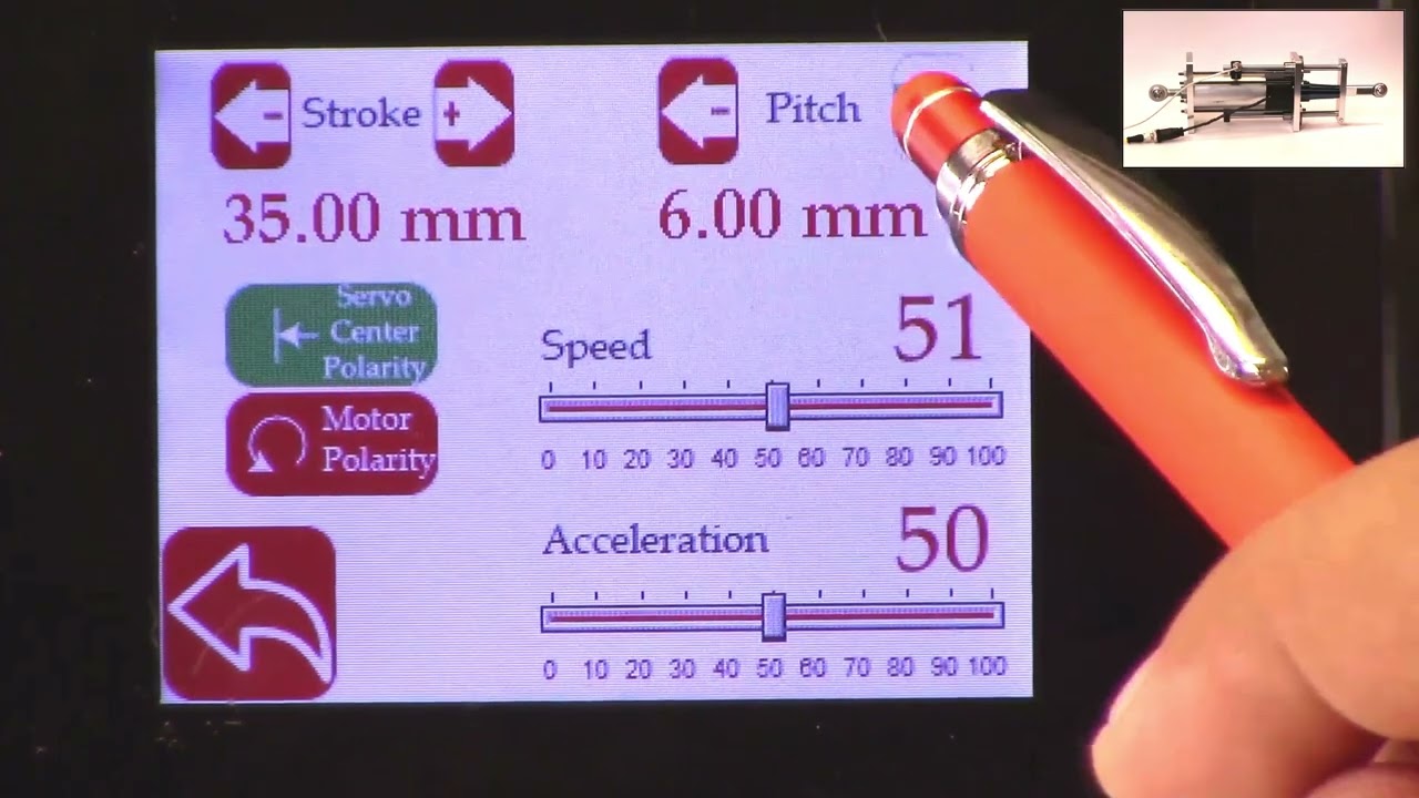
hello everyone this is arvind seshadri from Roll to roll Technologies today we're going to touch briefly about our actuator settings how do we set different parameters on the actuator on our scu5 all of our su5 controllers have the ability to connect to a variety of different actuators that are driven by stepper Motors we provide our own drivers for it if you look at our documentation you can see that from the su-5 controller we go to a motor driver through the motor communication cable and from the motor driver we go to the actuator through the actuator cable because we have the flexibility to connect a multiple different types of actuators we also provide the ability to set up some of the parameters of the actuator through our su5 controller that's what we're going to look at today and we're going to see how to set the stroke of the actuator the pitch of the actuator the speed the polarity and so on and so forth we do have our one of our actuator connected right now to the scu5 controller and that's the one right here and this is this is our standard upgrade kit actuator and this one has a front spherical eye and a rear spherical eye and then it has bearing supporting the the actuator to extend and retract and this is our LHS series with a four inch stroke this actuator also has a Servo Center sensor that is installed right here and that's actually looking at the rail that is going in and out the servo Center basically allows us to quickly Center the actuator or home the actuator to a position which makes the web guide be parallel to the other rollers within the machine we'll also go through that in another video but essentially we have our actuator connected here and then if you use our sc5 controller to move the actuator you can see that the actuator is moving back and forth and that's also seen on this bar graph right there so we'll take a look at how we're going to set some of the parameters that can be done by going into the tools icon and then power user and then actuator and this provides you with some of the settings that are currently available and this shows a pitch of 0.25 inch a stroke of 1.38 inch there's also a motor polarity setting here and then the speed and the acceleration but when we ship our controller we based on the actuator that is purchased we preset those values in the controller and ship it but if you want to change it it's pretty simple so for example if I want to change the speed I can just drag this right there and set the speed and we can also change the acceleration the speed and the acceleration can be changed independently and the pitch of the actuator is depending upon what the actuator is and that is basically one revolution of the motor how much is the actuator going to extend or attract in our case this particular actuator has a pitch of 0.25 inches and that's what it is set up there if you need to change the pitch you can just press this button and it's going to increment or decrement the pitch the units right now is shown is in inches and if you want to see those units in millimeters you can go to this screen hit the operator icon hit the display and change the units to millimeters and once you do that you can go back to the power user actuator and you can see that the actuator units are now in millimeters this is about 6.5 or 0.25 inch approximately and then the stroke is 35 millimeters and you can probably set it to the stroke on the actuator the stroke that you set is not the actual mechanical stroke that is available on the actuator this is just an electronic limit in order to avoid some of the pitfalls with existing some of the other actuators that are available where if there's issue let's say the web breaks the actuator may go back go to one side and it might keep driving because it has Reach This limit it doesn't know it has reached this limit and it keeps driving it and that might burn out the actuator to prevent that from happening in our case we actually have an electronic limit that means that if the actuator reaches its electronic limit whether the actuator whether there is a mechanical limit or not it will stop just to show you how that works I'm going to set the stroke to be some really small number let's say 30 millimeters and if I go back to the home screen and I try to jog the actuator you can see that it's going in and right now the actuator position is it's showing that it has reached it's fully retracted limit even though if you look at this actuator there's a lot of stroke remaining so if you look at here there's still a lot of room for the actuator to retract more but it stopped at this electronic limit just to prevent it from burning or destroying the motor so the electronic limit can be any limit that you set and that limit of whatever that the stroke that I showed again if I go back to the screen and to the actuator you can see that the 30 what that 30 means is that it's going to be 15 from the middle of the actuator position and on one side and then 15 on the other side and that's what the stroke means so if you are in the middle position of the actuator you can go 15 on one side and 15 on the other side that's what the stroke means in terms of setting there's also the polarity so what we can do is we can change the polarity and if you remember when I did this when I pressed the Plus it was going in a certain direction and if I do this when I press the plus it's actually extending in the previous case when I pressed the plus it was actually retracting and that's also shown here in this position when the polarity is the standard polarity the plus will increase the actuator position and that's what this is showing and the negative will decrease the actuator position so it's retracting if we reverse the polarity then it will do the opposite and again when we reverse the polarity that it clearly shows here now if we press the plus it's extending retracting and then if you do the minus it's actually extending so the polarity can be changed as I'm moving the jogging the actuator back and forth one of the things that you can notice is that the this bar graph changes color and right now it's in yellow or Amber and then if I go to another limit and now it becomes red this is more evident in the other direction so if I go all the way in the other direction this is going to be yellow and then if I go reach a certain it goes to Red this is a quick visual indication for the operator to know that the actuator is close to its extreme position if not at the extreme position if it's in red it's within 10 percent of the extreme position limit and if it is in yellow then it's between 20 percent to 30 percent of the extreme limit so we don't typically like to run the web guide in this position is that there's not enough room for correction in this direction so if there is an error in this direction and the actuator needs to move that way there's not enough room to correct for it so anyway a quick visual indication for us to see where the actuator is again if you want to see that in a bigger screen if you just click on that motor icon then you can see that the same bar graph that you saw on the home screen that's essentially the things with regard to the stroke and the pitch and the the speed and the polarity again just to reiterate there is a difference between the mechanical limits and the electronic limits the mechanical limits are the actuator cannot move anymore because it's mechanically inhibited and we never want to set that actuator or install the actuator in that scenario where the mechanical limits are reached the electronic limits are just safely limits and this allows us to stop the actuator from moving even before it reaches the mechanical limits so we typically suggest that you install the actuator move it back and forth find the Home position set the home position or this Servo Center position and then set a certain stroke and then jog all the way to one side make sure that it doesn't hit the electronical limits and jog all the way to the other side and make sure that it doesn't hit the mechanical limits and as long as it doesn't then the electronic limits are fine if in any scenario whether you're going jogging left or jogging right it hits the mechanical limits then you would have to reduce the electronic limits so we never get into that situation where the actuator might hit the mechanic that's all we need to do in terms of setting up the actuator in terms of the stroke and the pitch there are other few functionalities that are available for certain controllers for example the actuator position if it reaches the extreme position there is a way for us to set digital outputs so that not just an operator needs to look at it but the digital output can provide a signal to the PLC to alert PLC that hey the actuator has reached this limit the other option that we have this is mainly for our big actuators that are moving the unwinds and rewinds which are susceptible to damage if we reach the mechanical limit that we can add additional limit switches either mechanical limit switches or even electronic limit switches make sure that the mechanical limits are never reached and if we have that option if we have the hardware provided with your actuator then you have the ability to enable them the way to do that is to get into the tools and then the power user and then in the controller there's this limit switches icon button and then we just need to turn on the limit switches if you don't have the limit switches and you turn on the limit switches the actuator might not move just be aware of that but if you do have the limit switches and you want to enable that functionality then you can enable that functionality by turning on the limit switch so those are the basics of the actuator settings in terms of stroke pitch polarity limits and limit switches in a subsequent video we'll talk about the servo Center functionalities but in the meantime do subscribe to our Channel and we'll see you in the next video