In this episode of the Multiple Web Width Measurement Application Series, we showcase the advanced pattern teaching feature of the SCU6x controller. Learn how to set up widths, samples, and jobs to monitor changes in material movement and width accurately. Discover the advantages of the pattern teaching mode, such as alerting when a web breaks and maintaining precise measurements even with intervening materials.
Transcript
Show full transcript (485 words)
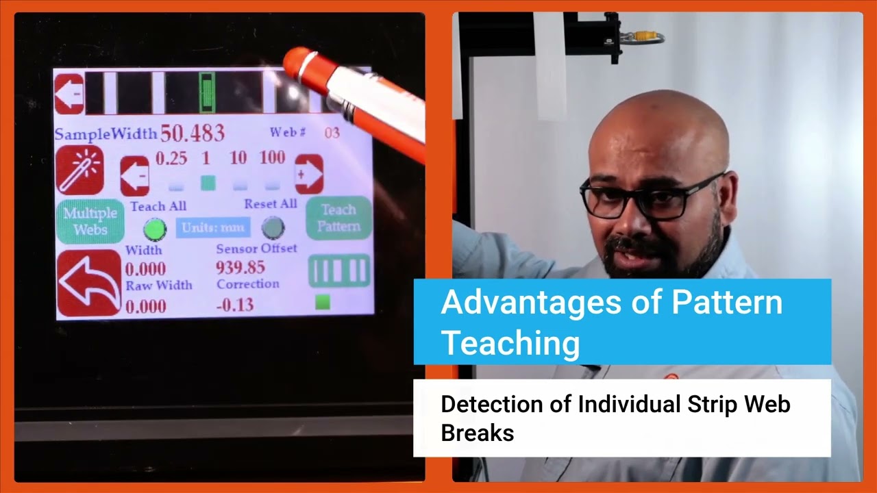
Now we do have another feature that allows you to get even higher um uh uh insight into your process and what that is what we call pattern teaching. So essentially what we will do with the pattern teaching is that we set the widths, we set the samples, we set the job. We're looking for not only the change in the width but also change in the movement of the material. You can enable that by pressing this button that's in the pattern teaching mode.
When you're ready to teach the pattern, we're going to press this teach pattern and press accept. So now the system is taught the pattern. What is the advantage of that? If I have uh let's say I'm in web 3, right?
And if the web three breaks right now, it is actually showing you that hey, I'm supposed to see a web there. It's broken. The value is zero. And it's going to provide an alarm or alert right there.
That's one advantage of that. Another advantage with that is that let's say I have a web five that I'm tracking right here and if I have another material that comes in between there, the web five's measurement is not affected by that whatsoever. In a typical camerabased system, they're going to keep track of the width randomly based on which one is first and which one is second. That would affect the measurement.
If I do have this pattern off, web five will actually jump. You saw that it jumped to that 10 mm and it jumps back. To avoid this jump, we are going to use the pattern. And once the job is set up in your slitter rewinder, it's not going to change.
The pattern is not going to change. Then even if something comes in, that gets completely disregarded. That's the advantage with the pattern teaching or pattern matching mode. Those are the key things with regard to how you can set up our SCS 6x controller for multiple slit width measurement.
Okay, one of the thing that we wanted to show is that this width measurement right now we are in pattern mode. So even in pattern mode, if the web moves back and forth, you can see that the web is moving, but it's also keeping track of that edge position, keeping track of that width pretty accurately. And we can actually move this quite a ways off and that's when it will say that the pattern is supposed to be there, but it has moved from its intended position. So this is an example where let's say the slitter blade moves too much then you can catch that.
Obviously it'll show up in the width but it'll also show up in the web position. As soon as we come back into that location, the actual location itself, then it locks in on that
In this installment of the Webinar on Web Guiding Fundamentals, we delve deeper into the pivotal role of controllers in web guiding systems. The episode covers the function of controllers, components such as gain, operating voltage, and sensor inputs, and explores the control structure for web guide systems, including fixed gain proportional control and adaptive control technologies. By examining open loop and closed loop responses, we highlight the importance of optimal tuning for improved performance.
Transcript
Show full transcript (917 words)
[Music] The controller is the central processor that takes the sensor input, computes the corrective action and sends that information to the actuator. Nowadays, the controllers also include human machine interface like an operator interface. Previously, the controller could be standalone. It didn't really have an interface.
So the controller could be analog in the sense of electrical analog or pneumatic analog controllers. So basically controller is taking the sensor signal and then making the necessary computation so that the actuator can be positioned at the desired location. In terms of terminology, gain is one of the most common things that you're going to hear in controllers. That's basically saying how quickly or what kind of a dynamic response you need.
gain is going to do that. Other things that you're going to see is operating voltage, power consumption, whether you have a operator interface or not. And then whether this is a controller for a servo motor or stepper motor, they have drives or drivers for it. How many sensor inputs you have?
Does it have Ethernet connectivity? Does it have remote control and stuff like that? In terms of the control structure, most control systems have webguide control systems have this kind of a structure where you have a fixed game proportional control. You really don't need more than a proportional control for a web guide because there's integrator built into it.
But usually you have something like you have a motor, it might have a current loop, it might also have a velocity loop with a tachometer. Then you have a guide structure which has its own transmission ratio. And there's the web dynamic which is unknown. Web dynamics means that if you move the guide 1 mm, how much is the web going to move?
That really depends upon transport conditions, the stiffness of the web, tension and all those kind of things. And then finally, you have a sensor that measures the edge position and then it sends that to a position controller. So this is a pretty simple architecture for most webguide controllers. They are fixed gain and most often they are d-tuned because of the stability and all the other reasons.
Most web guides their controller is kind of d-tuned for the conditions. If you want to get the best out of it, you would need to retune them. The tuning has to be based on the optimal performance because the web dynamics is unknown. Most often DC motors or DC servo motors or stepper motors are used in this kind of control structure.
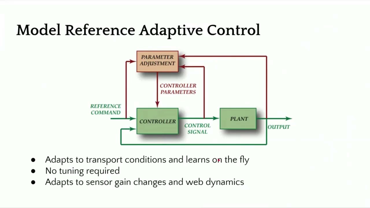
There are some other advanced control technologies like adaptive control where the controller can adapt or learn on the fly and tuning may not be required. When we say learning on the fly, it means that it adapts to sensor gain changes or the dynamics of the web. In our case, we have a similar structure as the one I showed first. It's still a fixed game controller, but with some motion control aspects built into it in terms of curving the position and having trajectories for velocity, we can increase the stability of the controller and provide a pretty aggressive output performance.
You can have a current loop, a position loop, if you have a encoder, and then a position of the actuator here. And finally, the web position, which includes the web dynamic. Just to give you an idea, we have a lot of different things that we can do with the controller. But the dynamics is basically if you move the this is showing a step response, openloop step response for a web.
This was like a non-woven web that we had at different speeds and see how it behaves. And you can see that when you have a step, even though it's open loop, it's trying to get there. The openloop dynamics is different based on how fast you're running. So faster you're running, it gets to that desired location uh as fast as possible.
But the slower you're running, it takes longer. Again, this is an openloop response. This is the final part of the whole web guiding, which is the dynamics of the web. Now if we add a controller to it then we can have a much better response and actually push the web guide.
In this case at the two different speeds that we were running at this was the reference change and this was the actual response of the web guide at the sensor. And then when we have another sensor installed once span downstream you can see how long it takes for that to go through. When we have a step response, we were able to get up to about 170 mm/s or like 7 in per second. This is about close to 70% improvement over an openloop response.
And again, this is closed loop. That means you're actually actively guiding the web. So with a proper control structure design, you can get a high bandwidth system close to 6 hertz or something like that and then even get a well damped system. So you can actually have an aggressive correction if you need to.
In terms of the characteristics of a good webg guiding system, it should have the ability to attenuate disturbances, easy to tune. Obviously, it needs to be stable, has good processing power so that it can process multiple sensors, have industrial Ethernet connectivity. These are for advanced functionalities. And then smart intelligence for industry 4.0.
[Music]
In this demonstration, we showcase the flag detection capabilities of Roll-2-Roll Technologies' SCU6x Controllers combined with ODC Sensors. The setup includes both unwinding and rewinding mechanisms, with a sensor monitoring the edges of the web. The SCU6x Controller is configured to detect flags effectively, ensuring accurate monitoring even with web oscillation. The video highlights the ease of setting up the system, the parameters involved, and the robust nature of the algorithm, making it a reliable solution for web handling applications.
Transcript
Show full transcript (1186 words)
So what we have set up here in this um demo test setup is um we have an unwind and a rewind. We have added some um flags. Uh there are some flags on the left edge. There are some flags on the right hedge, right edge of the web.
We have a single sensor right here that is looking at the web. And then we do have an SEU6X controller that is set up uh for this flag detection application. So this is the same controller that we looked at in u previous videos. Um I'm going to just quickly walk through how we can set this up for flag detection.
As you can see, we have the um uh sensor one connected. So and it's been set up to center mode because we have a wide enough sensor that can see both edges of the web. And uh um in order to do the flag detection, we're going to go into the tools icon operator on the top right and then the flag detection. So this is the screen where if you are using this just for flag detection applications, then you can be on this screen and monitor it.
But you can set this up, an operator can set this up and you don't have to be on this screen for the flag detection to work. So there are a few things here. Uh just like the home screen, you see a realtime uh preview of where the image is. And since our sensor is looking at both edges of the web, you also see the center line position right there.
Um and then when the flag detection is running, let's say there is a flag, then this flag detect signal would come in. So just to illustrate that, I'm going to artificially create a flag right there. And you can see that the flag detection signal lights on. uh the the duration for which the flag detection is on is called the hold period.
So you can set up all of these. So I'll go in and show you how we can set that up. If you hit the tools icon there, then it's going to bring into this screen. And this is basically where we define certain things.
So what is the minimum length of the flag? Uh when we say length, it's basically how much um uh in distance is it protruding from the edge of the web. So this is in the cross machine direction length. That's what we are talking about.
So if the edge position is in a certain location, how much more is the minimum flag length? Right now we have set it up to 5 mm which is pretty small. Uh depending upon what your application is. Typically for our customers uh it's anywhere from 25 mm which is an inch all the way up to 2 in.
Um but you can set up whatever length you want. And this just means that if the web moves suddenly within this length um or this uh length in the w um cross dimension, it will not trigger a flag. So um the reset duration is basically uh allowing the uh the controller to automatically adapt to wid changes. So if you have a machine running and then you do a on the-fly wid change then instead of um you coming back here and saying hey the new web position is this new location because the width changed uh you can actually set up a reset time.
Essentially that means that for this amount of time if that web position is in this new location we're going to say that that's the new web location. So typically you can set it up anywhere from 5 to 10 seconds. So we'll set it up at 5 seconds. And then hold output.
This is um essentially for um you to take the signal into your PLC. Uh whenever a flag is detected, we output a signal. How long do you want to keep that signal on? That's essentially the hold output duration.
So we will typically set it to 1 or 2 seconds. This really depends upon your PLC and uh if you have a high speed data acquisition system or not. Uh but if you increase the whole time, it just means that uh you guarantee that your PLC is fast enough to see that. So that's essentially it.
That's all the parameters that we have for this. And um if we are now running the machine um we would see that it will start picking up the flag. As you can see there's a flag coming up right now. As the flag goes through um the stack light gets triggered and the stack light is on for the duration that you set so that your PLC can miss it.
So this flag right now that went through was just on the left edge. Here's now on the right edge. You can see that it's picking that up. Just to show you how that works on the controller screen.
Um you have this same kind of an output. When the uh flag comes through, it gets triggered. And um when there's no flag, it's out. And then when the flag comes through, it gets triggered.
You don't necessarily have to be on this screen. Like I mentioned, you can be on a different screen. And this will still trigger the output because that's running in the background. Uh that's essentially it uh in terms of uh uh flag detection.
So just to give you an idea about how robust this algorithm is, we can even set it up to oscillate the web and it will disregard the oscillation and still detect the flag. So I'm going to do that. So now the web is oscillating back and forth. As you can see it's moving.
The flag detection is not getting triggered. When the flag comes through it gets triggered. As simple as that you can have flutter. You can see that the web plane changes quite a bit.
Even then the flag doesn't get triggered. Only when a flag comes through the stack light gets triggered. So just a pretty robust way to detect a flag. Um and you can see that um whether it's left edge, right edge, the sensor automatically knows which edge it is and it detects the flag and provides an output.
So again, Roll to Roll Technologies, we are here to provide you with solutions that are simple to use, robust. Uh we do the research so that you don't have to spend time on trying to um make the machine run just like how you want it to run. uh we do all the heavy lifting so that it's even an operator can set this up and it it doesn't take that much time for you to get this up and running. Um hope you like this video.
If so, make sure to uh like and subscribe to our channel and uh stay tuned for more videos. Thank you.
How to Access the Operator Width Screen
In this video, we guide you through the steps to access the operator width screen from the home screen. Start by pressing the tools icon, followed by the operator icon located at the top right, and then the width icon. You'll first arrive at the operator width home screen, and there's an additional setup screen available where you can perform further setup tasks.
00:00 Accessing the Operator Width Screen
00:17 Operator Width Home Screen Overview
00:21 Additional Setup Screen
Transcript
Show full transcript (57 words)
To get to the operator width screen from the home screen, we're going to press the tools icon, then the operator icon on the top right and then the width icon. This first page is the operator width home screen. The second page is an additional setup screen where you're able to do more setup related things.
SCU6x Controller Calibration for Precision Width Monitoring
Transcript
Show full transcript (800 words)
One other thing we need to do whenever we are initially setting up is um onetime calibration procedure that can be done on this screen. The idea for this is that we have the ability to calibrate our sensor for your conditions. We do have a calibration done in the factory, but when it's being installed, the sensor might be installed at a different distance than what we typically expect. And there are other things with the lighting and contrast that might change some of these parameters.
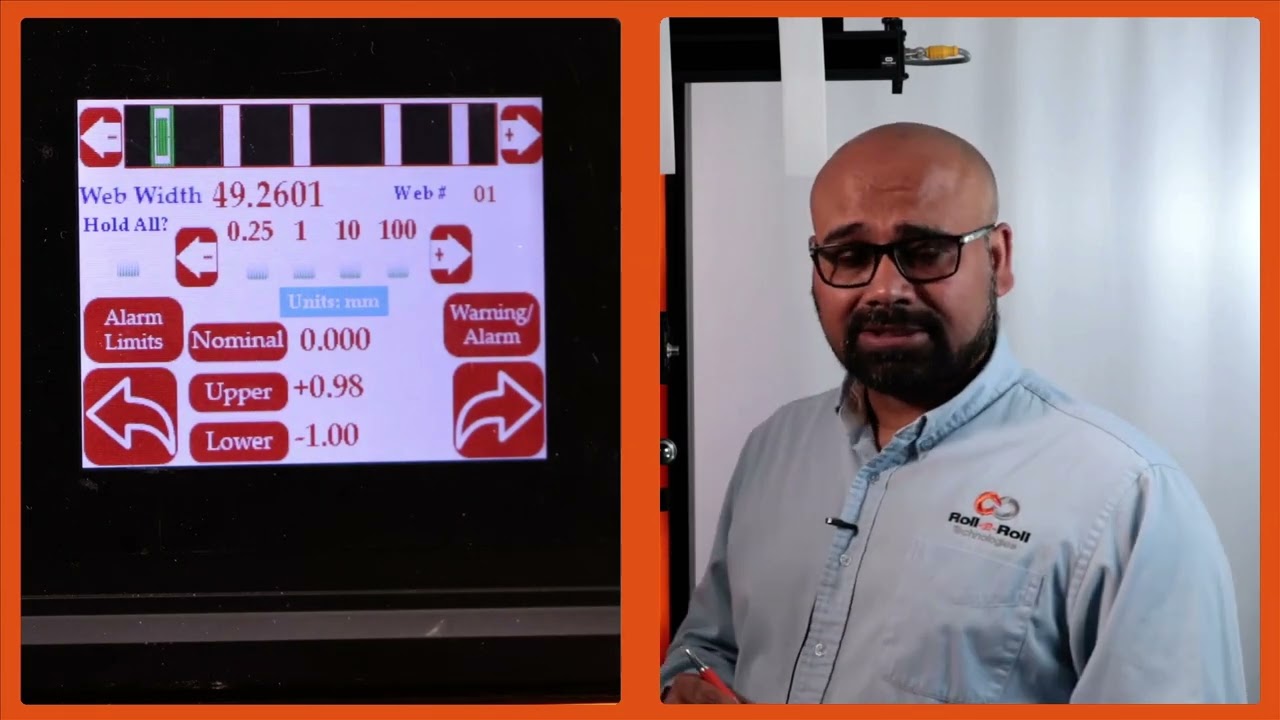
So, this calibration is necessary only if you're looking for a higher resolution measurement. For example, if you're looking for a tolerance of plus or - 1/16th of an inch, you don't need to do any of these calibration things. But any anytime you are below that. So anytime you're below a millimeter or below a 1/16th of an inch resolution, you would need to do a calibration.
This is done just for that particular setup. Once you do it, you don't have to do it for the rest of the run. It'll be stored and you take that calibration value. What does the calibration do?
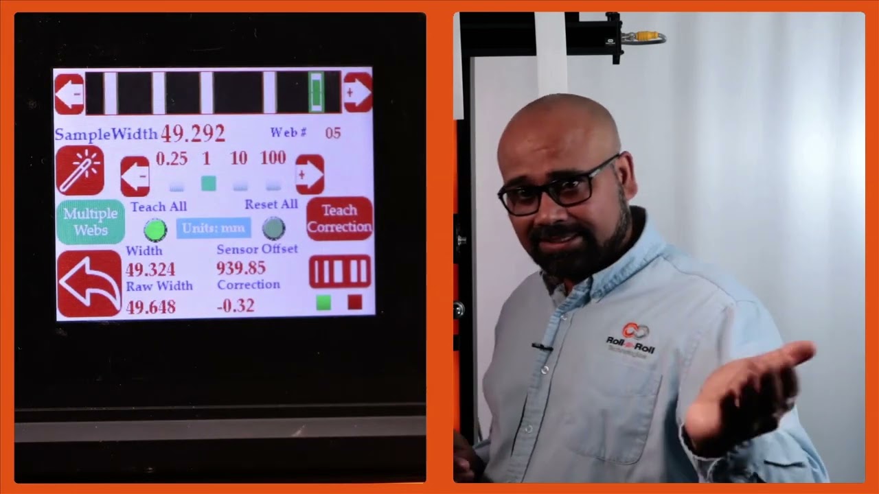
Essentially, I have a material or a sample of a known width and the sensor is providing a raw measurement. We're going to compare those two and then say the calibrated measurement is based on the actual sample width and whatever the raw offset is, that's the correction we are going to use for the rest of the measurements. So that's indicated here. So that's basically saying what is the correction from the actual width to the measured width.
That's essentially what the calibration is. So it's just creating a offset. So for example, let's say the sample width is 46. To change that, you press whatever you need to increment by and change that value.
I am going to put that as 49.244. Right now it's measuring 49.293. If I want to teach this, my sample width should match my measured width. To do that, press this teach icon and then press accept.
Now it has applied a correction. Essentially the raw width plus this correction gives me my actual width. And that's pretty simple. It's just a regular bias or correction that we are adding.
Nothing fancy about this calibration. So you can do that for all these other materials. We don't necessarily need to do this if your tolerance is 1/16th of an inch or 1.5 mm. We don't need to do that.
But for some customers looking for a higher resolution, you do that calibration procedure. Now, just to make it simple, you can enter all of these sample widths already and then you can do a one-time teaching. Let me show you how that works. I'm going to enter this sample width here.
Okay. So, if I want to do all of them together, I'm going to press this teach all button. Make sure that it's highlighted. And then I'm going to press this teach and accept.
Now, all these samples will have a correction. Before we had everything as zero. And if I now scroll through web five, web 4, web three, web two, and web 1, all of them now have a correction. So it's just a quick way for you to do this.
The general use case for this is that let's say you are a customer in automotive or medical and you have a QC process where you are only sampling a part of your product. You are setting up your slitter. You pull the initial sample after the operator has set up the slitter and you take that sample and you're doing a QC on that. Now, essentially what you're going to do is take that sample and enter it like what I have here.
Then you're going to do a teach all. Once that is done during any part of the run, we are taking that measurement online in line 100% of the time. So that's the biggest advantage with this system. In your typical process right now, you might be doing one sample at the beginning of the run.
At the end of the run, the operator needs to stop the machine, take that sample, give it to QC, take the measurement, and then everything is good. You run it, and then every time the machine is stopped, there is another sample that is taken. So, this is a random sampling process with a lot of time involved between one run to another. and we completely eliminate that and allow you to keep running the machine and monitor the width all the time.
So that's the biggest value proposition with our system. And that's essentially it. So that will allow you to calibrate each of these samples and be done with it.
Exploring the Dual Rail Power Supply Feature of the SCU6x Controller
In this video, we delve into the dual rail power supply feature of the SCU6x Controller. This feature provides a separate power rail for the driver and the logic, enhancing safety by allowing the power to the driver part to be cut off when necessary, such as during access to a web guide. Demonstrations include how to indicate power status and control the actuator via this dual rail system.
Transcript
Show full transcript (501 words)
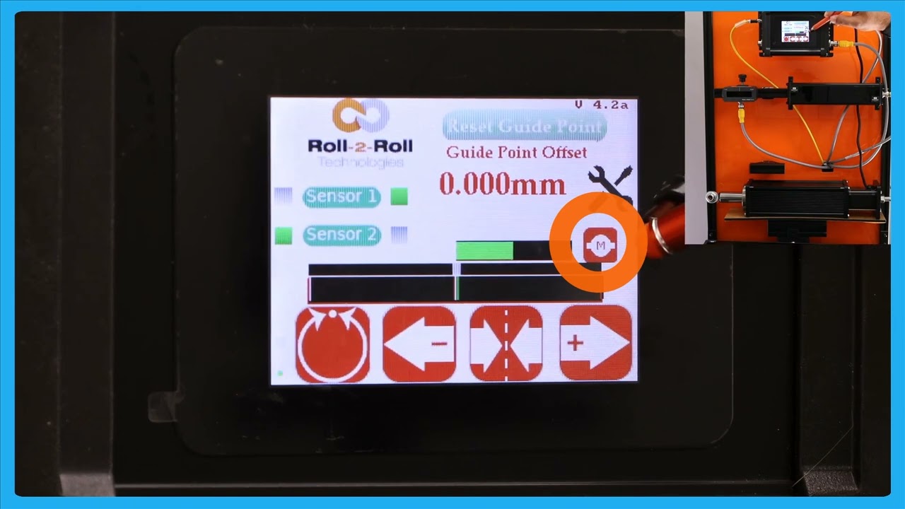
hello everyone this is Arin sadri from Roll to roll Technologies today we're going to talk about a couple of different features that we have we're going to see one of the features of the seu 6X controller wherein we can have a dual rail power supply this means you have one rail of power supply for the driver and one rail of power supply for the logic or the controller the main reason why somebody would have this is in the cases of safety so let's say you have a web guide inside a guard door and you don't want the web guide to move when the car door is open or somebody is accessing the machine close to the web guide we can cut off the power supply to the driver part this is mainly for safety reasons if you're familiar with our SCU 5 controller you would know that this particular motor icon would be r in that case any seu 6 firmware version more than 4.2 will have this power indicator so this green power indicates that there is power to the drive the power to the logic is powering the display itself so now I can move the actuator back and forth and you can see that the actuator is moving and if you want to cut off the power supply to the drive I can do that I have a switch here that would cut off and now the power is cut off to the actuator and that's indicated by red and now if I try to move the actuator I won't be able to move the actuator and as soon as the power is turn back on and you get that green signal there and the power is on now I should be able to move the actuator so that's essentially it this is the feature where you have the dual rail power supply that allows you to turn off and on the second rail which is the driver rail in the SCU 6X mxd controller we do have the option where we have a separate Port that powers that which is a 48 volts DC power supply again we can do the same functionality there if the power is cut off to that rail then we would be able to see that indication on the screen this dual rail power supply feature is only available on the seu 6X controllers with firmer version 4.2 or higher this means that there are some older hardware and older firmware where you won't be able to see that feature or you won't be able to have that same functionality in those cases you can still use the second rail to turn off power and turn it back on the only caveat to that is there is no IND indication of whether the power is there or not so all of this features available any controller with the firmware version 4.2 or higher and both for sc6x MD and sc6x mhd

A Common Customer Concern, Controlling the Actuator when the Web Breaks
In this video, we address a common customer concern about actuators in the event of a web break, focusing on the safety features of the SCU6x Controller. We cover how the actuator will not drive to a mechanical limit due to electronic limits, preventing burnout.
Transcript
Show full transcript (510 words)
One of the common questions that we get asked from our customers is about our actuator in the sense that if the web breaks will the actuator keep driving to one direction or not. We saw that feature before where if we enable that lock on lost edge when the web breaks the actuator doesn't move and stays put. Now in the scenario where you don't have that enabled will that drive the actuator to its mechanical limit? The answer is no.
We have electronic limits set on the actuator. That means that even if there is no web, the actuator is only going to go to its electronic limit and it's not going to go any further than that and it's going to stop there. So there is no issue with the actuator burning out or anything like that and hitting the mechanical limit. These are artifacts of older web guides which does not have that intelligence.
Ours is all digital stepper motorbased system and we have a lot of options where we are able to have complete control over the actuator position and we can set those electronic limits to avoid the actuator hitting any mechanical limits. For those customers who want a little bit more safety conscious thing where they want to have limit switches, we do have that option. So this controller SC SU6X controller allows you to connect two limit switches apart from the servo center proximity sensor. And these limit switches, even though we call it switches, they're not mechanical switches.
These could be any NPN proximity sensors that just looks at a flag that's going to tell what the limit is. So you have a left limit switch and a right limit switch. When we have that enabled, if the actuator is going in the left direction and hits the left limit switch, it will not move anymore. This limit switch would be a proximity sensor.
As soon as that flag is seen by the proximity sensor, in that left direction, it will not move. It will still move in the right direction, but not in the left direction. This is an hardware implementation. So there's no software involved in this.
Even if our system has some things that we have set up, it'll be an hardware limit there. Likewise, you have a right limit switch, which is an NPN proximity sensor. When the actuator moves and brings a flag in front of the right limit switch, the actuator will stop automatically. So, it's more like a belt and suspender and suspender approach.
So, you have three different options. One is the actual stroke limit on the actuator electronically and then you have these limit switches and obviously you have the lock on lost edge. All of these things is going to allow you to be able to have a longer life for the actuator and this is again with the advances that we have with our controller. We have a lot of flexibility in controlling the actuator and increase its life.
In this episode, we explore how to utilize the center guiding feature of the SCU6x Controller with two sensors, focusing on automatic adjustments and setup. We demonstrate the mechanics of center guiding using an actuator and explain the importance of using sensors of the same range. With detailed visuals, we show how to reset the guide point and align the material to the center of the machine.
Transcript
Show full transcript (1038 words)
So, one of the other things with the SC6X controller is that we can do center guiding with two sensors and it can be done automatically. We talked about how to set up the different sensors for different configurations. So, please take a look at those videos. In this video, we're just going to show you how it works with an actuator, how things look, and how to reset the guide point for center guiding.
What we have is a couple of sensors connected here. One of the things with center guiding is that we would like the two sensors to be of the same range. Even though the system would work when you have two different ranges just on the display to make it simpler and not cause any confusion, it's better to use two sensors of the same range. Right now, I have an infrared sensor and a white light sensor just for illustrative purposes.
In reality, anytime we are doing edge or center guiding based on the edge of the material, we're going to always use an infrared sensor. So, let's go back to the screen and see how it looks. This sensor is set to see the left edge and this sensor is set to see the right edge. So, if I have a material that is presented, you can see that it's seeing the left edge and the right edge.
The green in the middle is showing the center line position. And in this particular case, we got the guide point offset to be zero. So if I set it to automatic, then the actuator is going to move back and forth based on if the center position is within the guide point to the left or to the right. And that's essentially how the center guiding works.
There are two main reasons why somebody would use center guiding. One is if you're changing web widths and you want to align the material to the center of the machine, then center guiding is the best option where you would place two sensors on either side and the those sensors are equidistant from the center line of the machine. So when the web width changes, you don't ever have to move the sensors and it automatically adjusts itself because it's going to look at the left portion of the web seen by the left sensor and the right portion seen by the right sensor. This is one of the common features that we have or common value proposition from our products is that our sensors can go anywhere from 48 mm up to 960 mm.
That means you can have a width change of about 96 mm up to about 1920 mm without needing to move the sensor. This provides a lot of range and flexibility to be able to have a system that can adapt to wick changes on the flight. The older generation systems might have some actuators that move the sensors based on the wick change. And more often than not, what happens is that those actuators have their own control loop that needs to be tuned.
The actuators can wear. These are the actuators for the sensors that could wear over time. And that creates an issue. And then the response time, especially when you do a wid change on the fly with those kind of systems, is going to be much lower than compared to a system with a sensor that is wide enough to cover all the width changes.
So that's one of the main reasons for using center guiding is that you can do different widths without moving the sensors whenever the width changes. The second main reason why you would use center guiding is that let's say you have an edge especially some kind of an extruded edge and the edge quality might not be great. So before it goes into a slitter you you have an edge and the edge is not that great. Instead of aligning to one edge of the web, in that case if you use two sensors and then use the center line position, it takes the average of the left edge and the right edge and does the measurement that is going to be the center line measurement and it's going to guide the web to the center.
This is one of the biggest advantage for using two sensors and doing the center guiding and especially when you have irregular edges, those edges variations are not going to be identical on both sides. This smooths out your edge profile and allows you to guide the web in the middle of the machine and that significantly improves the wound roll quality especially if you don't have a pretty good slit edge. So the advantage is that you are averaging based on two edge measurements and this helps in smoothing out the edge position. Those are the two main reasons why you would use center guide.
One of the other things that I want to show with center guiding is that you can do the reset guide point just like what we did with edge or center guiding with two sensors. Let me show you that. Going back to the screen here, we have the web now and the green position indicates the center line position. If the web is moved that way and for whatever reason you need to do that, you could do the same reset guide point and accept.
Now the guide point offset is there. If the edge position goes on either side, the actuator changes its direction back and forth. This is for doing the center guiding with the point offset. Now, like I said, it's not usual for you to change the guide point offset with center guiding just because you want the material to be aligned to the middle of the machine.
The reason why we allow you to do that is that let's say you had not installed the sensor at the right location to begin with. Instead of going and physically moving the sensor, you could just move the offset. And that's the reason why we allow a guidepoint offset even when we do center guide.

In this video, we explore the two main reasons for using center guiding in web handling systems, focusing on the advantages it brings when dealing with varying web widths and poor edge quality. The SCU6x Controller's advanced sensor technology allows seamless adjustments without the need to move sensors, accommodating significant width changes efficiently. This ensures high response times and minimizes wear on actuators.
Transcript
Show full transcript (529 words)
there are two main reasons why somebody would use Center guiding one is if you're changing web widths and you want to align the material to the center of the machine then Center guiding is the best option where you would place two sensors on either side and this those Those sensors are equidistance from the center line of the machine so when the web width changes you don't ever have to move the sensors and it automatically adust adjust itself because it's going to look at the left portion of the web seen by the left sensor and the right portion seen by the right sensor this is one of the common features that we have or common value proposition from our products is that our sensors can go anywhere from 48 mm up to 960 mm that means you can have a WID change of about 996 mm up to about 1920 mm without needing to move move the sensor this provides a lot of range and flexibility to be able to have a system that can adapt to Wick changes on the flight the older generation systems might have some actuators that move the sensors based on the wick change and more often than not what happens is that those actuators have their own control Loop that needs to be tuned the actuators can wear these are the actuators for the sensors that could wear over time and that creates an issue and then the response time especially when you do a WID change on the fly with those kind of systems is going to be much lower than compared to a system with a sensor that is wide enough to cover all the WID changes so that's one of the main reasons for using Center guiding is that you can do different widths without moving the sensors whenever the WID changes the second main reason why you would use Center guiding is that let's say say you have an edge especially some kind of an extruded Edge and the edge quality might not be great so before it goes into a slitter you you have an edge and the edge is not that great instead of aligning to one edge of the web in that case if you use two sensors and then use the center line position it takes the average of the left Edge and the right Edge and does the measurement that is going to be the center line measurement and it's going to guide the web to the center this is one of the biggest Advantage for using two sensors in doing this inter guiding and especially when you have irregular edges those edges variations are not going to be identical on both sides this Smooths out your edge profile and allows you to guide the web in the middle of the machine and that significantly improves the wound roll quality especially if you don't have a pretty good slit Edge so the advantage is that you are averaging based on two Edge measurements and this helps in smoothing out the edge position those are the two main reasons why you would use Center guide
Resetting the Guide Point in Center Guiding with SCU6x Controller
This video explains how to reset the Guide Point in Center Guiding using the SCU6x Controller. It demonstrates the process of center guiding with two sensors and showcases how to reset the guide point and adjust the offset. You'll learn how to manage the actuator direction changes and understand the reasons for allowing a guide point offset even when aiming for center alignment.
Transcript
Show full transcript (209 words)
One of the other things that I want to show with center guiding is that you can do the reset guide point just like what we did with edge or center guiding with two sensors. Let me show you that. Going back to the screen here, we have the web now and the green position indicates the center line position. If the web is moved that way and for whatever reason you need to do that, you could do the same reset guide point and accept.
Now the guide point offset is there. If the edge position goes on either side, the actuator changes its direction back and forth. This is for doing the center guiding with the point offset. Now, like I said, it's not usable for you to change the guide point offset with center guiding just because you want the material to be aligned to the middle of the machine.
The reason why we allow you to do that is that let's say you had not installed the sensor at the right location to begin with. Instead of going and physically moving the sensor, you could just move the offset. And that's the reason why we allow a guidepoint offset even when we do center guide.