Roll-2-Roll Technologies introduces their sophisticated splice detection system using the 1DC480 sensor. Demonstrating at speeds up to 1000 feet per minute, the video showcases the sensor’s capability to detect various splice types, including bright, dark, and transparent splices, alongside voids and defects. The sensor's versatility is highlighted as it differentiates between splices and web instability without the need for reconfiguration.
Transcript
Show full transcript (1449 words)
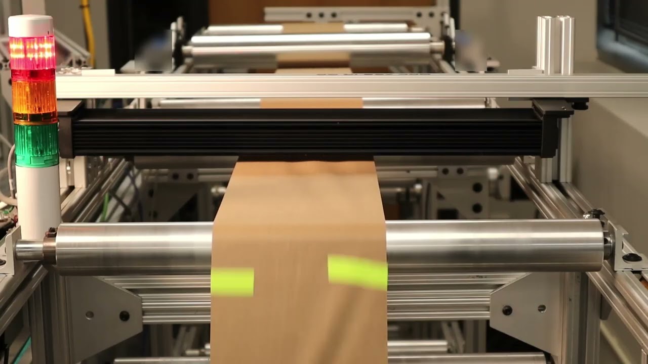
Hello everyone, Arvvin Shadri from Roll for Roll Technologies. Today we're going to show a little bit about our splice detection system. Right now we have the 1DC sensor set up so that it can detect a splice. We just [music] saw a thing splice go through.
Whenever the splice is detected, we have a stack light and the output from the 1DC sensor is triggering a stack light. Apart from a splice, we can also detect voids or defects. You saw a big hole go through and a couple of labels go through right [music] now. So essentially, we can look at some surface defects by looking at the image we are getting from our 1DC sensor.
There's another hole coming through or tear was able to detect that. We have some [music] web instability like you see there. a little bit of a standing wave of wrinkles going through, but that is not being triggered. The sensor is able to distinguish between a splice and some web [music] instability and not trigger for that web instability.
At this point, we're running at about 200 ft per minute just to give you an idea of how the system [music] works and also for you to actually see the splice as it goes through. What we are going to do a little bit later is that [music] the same set of splices. We're going to run it at a much higher speed and see how that works. We do have different types of [music] splices.
Essentially, there's no setup. There's one condition it has been running on [music] and it can detect a hole, a bright splice, a dark splice, a transparent splice, and even a butt splice. So, we do have a transparent splice that is going to come up here. I'll point out when it comes up, but doesn't matter what it is.
Unlike other splice detection systems, we are able to detect all of these different types of splices without making any changes to our controller or the sensor configuration. our 1DC sensor which is 1DC 480 which has [music] about 7,600 pixels and all of this is running at about 200 [music] times a second. So even a bud slice or a really difficult to detect transparent splice, we're able to see [music] that. And sometimes it might be a high contrast splice like a pink material that we are seeing right here and we were able to see that.
The main challenge with splices is that the splices can have different colors. It can vary in the contrast difference between the material and the splice itself. And sometimes it's a hidden splice. That's what we're [music] going to see next.
We have a bud splice where we we have a double-sided tape that is going through right here. It came through. And [music] you have uh two layers of material on top of a double-sided tape. So, you don't even see the tape.
You see the material. It was able to pick that up. And just to give you an indication about different colors, we have a dark color splice coming through and it still picks it up. The other common thing that we get asked about is that how long of a splice tape can we detect?
So, for example, right now we're going to have a shorter tape, a darker shorter tape [music] that comes through. It's able to detect that. That's about a 1 in tape going at 200 ft per minute. We can also detect darker colors or tapes.
As long as there is a contrast difference between the material and the tape, we'll be able to detect that. That's what we want [music] to showcase. Here we have a darker tape coming through. As you can see, it can detect that, too.
Sometimes the [music] splice may not be on the right side. In this demonstration, we're going to show that as well. And obviously, a smaller splice tape, can we detect it? We'll look at tapes coming on different sides of the material and can we still detect that or not?
Another darker one came through. [music] We're able to detect that. While we run this, this is at a slower speed so that the user can actually [music] see the splice. Once this is done, we're going to run it at a much higher speed.
So, this particular sensor, ODC 480, like I mentioned, it's running at 200 hertz or 200 times a second. So, it's able to capture the image, process the image, and send an output within 4 milliseconds. If we have a smaller viewing area, it can run faster up to about thousand hertz of [music] processing speed with these sensors. We are taking that input, processing it [music] and sending an output through EtherCAT.
In this case, this output is connected to our PLC and then the [music] PLC is actually triggering the flag. Now, here's an example where the splice is not on the right side. If you caught it, you can see that the splice was on the other side of where that camera was looking at. Just to give you an example again, another one where the splice was on the other side and we're able to detect that as well.
There is a little bit of splice tape that was folded over and we're still able to pick that up even though the splice is not on the right side of it. just to highlight the versatility of our sensing system in order to be able to detect the different types of splices, different variations in contrast, the way that an operator would do that. Now, another transparent kind of splice coming through. Here we have a transparent tape that [music] is splicing together the material.
And as you saw, it was still able to pick it up and do it. Another one where the splice is on the wrong side. We're still able to pick it up. We can't guarantee that it'll pick up all the time, but most of the time we can still pick it up.
And that's what we are trying to demonstrate here. Another example of a splice. It's a transparent tape and then splice on different spaces. We're able to do all of these.
So, this is just an example of how our splice detection works. In the following, we will speed it up and run it at thousand feet per minute. So you can see how it's able to perform even at higher speed as long as we're able to see it. Again, another transparent splice coming through.
And we can also detect some holes as we saw before. We're able to see some holes and tears and essentially void detection and anomaly detection. All of these things we'll be able to do. So, let's now look at [music] it at a higher speed and see how it does.
Now, we ramped up,000 [music] ft per minute. Some 1 in gray tape went through. A 1in spring tape went through. A 2-in gray tape went through.
A 1-in gray tape went through a dark green splice, a budge slice, a pink tape, a transparent one. Now we are at the end of the roll, so we're going to slow down and then reverse direction again. And there was a label that went through and then a hole or a tear label went through. And then another pink tape.
Now the machine is going to pause and then it's going to go in the reverse direction. And we'll see the same thing in the other direction as well. Heat. Heat.
Here you go. all these places at full speed. So we were ramping up from anywhere from 500 feet per minute to 750 and the max speed was about,000 ft per minute, we were able to catch all the slices, [music] even the butt slice at 1,000 ft per minute. The main thing is that even if the contrast [music] difference between the material and the splice is low, this algorithm that we have for splice detection is able to catch that.
And best of all, you can use this not only for detecting splices but also tears in the web, holes in the web, voids in the web. And we'll have more videos talking in detail about this. Once again, Arvin Sashadri from Roll to Roll Technologies. Take a look at our 1DC sensor [music] for more information about how you can use it not only for edge detection, width measurement, but also defect detection like splice, void, stairs, and the foreign matter on the material.
Make sure to subscribe and enable the notification. Thank you.
Unveiling the Advantages of the SCU6x Controller & ODC Sensors
Transcript
Show full transcript (296 words)
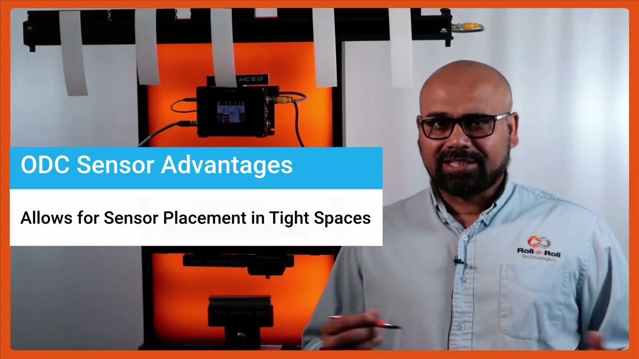
One of the key things with our SC6X controller and the ODC sensors is that [music] they not only are used for guiding purposes, they're also used for any type of cross machine direction width measurement applications. It could be measuring the width of a single web or multiple webs. Here again to reiterate on some of the advantages of the ODC sensor is that it's a one-sided sensor technology. So it allows us to install the sensor in tight installation spaces whereas a camerabased traditional machine v machine system might need a long longer field of view and working distance which creates issues if you want to add an width measurement system to an existing machine.
The other advantage is that the light source, the optics and the camera, everything is built into a single interface like what we have here. We don't have to have a separate light source or gantry [music] to have the camera and the light source built in. The third advantage is that the sensor provides a one one magnification. If the object is 100 mm wide, we're using a sensor that is at least 100 mm wide.
So, we get a one one magnification. The advantage is that when you go to a wider width, you don't lose any resolution. So for example, this ODC 960 which is a measuring range of 960 mm can provide the resolution of 127 micron on the camera level and then sub pixel with that you could get up to about 33 micron resolution. your resolution is not affected by the field of view that you are requiring.
Because of these advantages, the ODC sensor is used for a lot of different applications, especially in existing slitter rewinders where you want to measure the width of the material.
In this episode of the Multiple Web Width Measurement Application Series, we showcase the advanced pattern teaching feature of the SCU6x controller. Learn how to set up widths, samples, and jobs to monitor changes in material movement and width accurately. Discover the advantages of the pattern teaching mode, such as alerting when a web breaks and maintaining precise measurements even with intervening materials.
Transcript
Show full transcript (485 words)
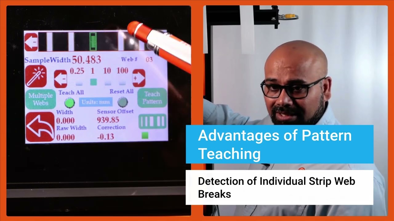
Now we do have another feature that allows you to get even higher um uh uh insight into your process and what that is what we call pattern teaching. So essentially what we will do with the pattern teaching is that we set the widths, we set the samples, we set the job. We're looking for not only the change in the width but also change in the movement of the material. You can enable that by pressing this button that's in the pattern teaching mode.
When you're ready to teach the pattern, we're going to press this teach pattern and press accept. So now the system is taught the pattern. What is the advantage of that? If I have uh let's say I'm in web 3, right?
And if the web three breaks right now, it is actually showing you that hey, I'm supposed to see a web there. It's broken. The value is zero. And it's going to provide an alarm or alert right there.
That's one advantage of that. Another advantage with that is that let's say I have a web five that I'm tracking right here and if I have another material that comes in between there, the web five's measurement is not affected by that whatsoever. In a typical camerabased system, they're going to keep track of the width randomly based on which one is first and which one is second. That would affect the measurement.
If I do have this pattern off, web five will actually jump. You saw that it jumped to that 10 mm and it jumps back. To avoid this jump, we are going to use the pattern. And once the job is set up in your slitter rewinder, it's not going to change.
The pattern is not going to change. Then even if something comes in, that gets completely disregarded. That's the advantage with the pattern teaching or pattern matching mode. Those are the key things with regard to how you can set up our SCS 6x controller for multiple slit width measurement.
Okay, one of the thing that we wanted to show is that this width measurement right now we are in pattern mode. So even in pattern mode, if the web moves back and forth, you can see that the web is moving, but it's also keeping track of that edge position, keeping track of that width pretty accurately. And we can actually move this quite a ways off and that's when it will say that the pattern is supposed to be there, but it has moved from its intended position. So this is an example where let's say the slitter blade moves too much then you can catch that.
Obviously it'll show up in the width but it'll also show up in the web position. As soon as we come back into that location, the actual location itself, then it locks in on that

Setting Nominal Width, Upper and Lower Limits for Multiple Web Width Measurement
Transcript
Show full transcript (798 words)
Then like I mentioned for each web we can set an nominal width, upper limit and lower limit. Right now I'm going to show you how we can set those things. So in order to set the nominal width we're going to press that nominal width icon and then we're going to choose how much increment we want to make. So I'm going to do 10 mm increments here.
So I'm going to change that to 50 mm. Okay. So the nominal width is 49.24. That's it.
There's no need to save anything here. Anytime you change that, that parameter is automatically saved and saved into the memory. So when you power cycle it, it comes back in. Likewise, you can set the upper limit and the lower limit.
So you choose the parameter that you want to change and pick the increment. If I do 1 mm increment that's going to be like that and you can do it like that. It's very simple intuitive way to change it. And likewise you can change those things too.
Now there are applications where we would have two types of outputs. One is to say that if my width is above a certain upper limit or if the width is below a certain lower limit you want to trigger an output there. So in those cases we would have something what we call as that upper limit lower limit kind of thing. So this is a pretty simple setting.
All that we are looking for is hey if the width goes above my upper limit trigger an output or if the width goes below the lower limit trigger another output. So just two boundaries and then within the nominal range the output is not triggered all good signals are provided. If you want an additional layer where you want to set alarm limits and warning limits then we can do that too. So in this particular case then you need to make sure that it is in alarm and warning.
When you have this in alarm and warning you have this button show up just to show you one one more time. If I have it just on upper and lower limit these are the two parameters we can enter. But if we are in warning and alarm there are four parameters you can enter. The first two parameters are here and the second two parameters are warning limits.
warning signal so that you don't have to stop the machine when the warning signal is there. This is just for the operators to know something is getting to get bad and once it hits the alarm limits then you can stop the machine if you wanted to. Just like I mentioned the warning limits are going to be closer to your nominal width and the alarms are typically farther away from there. So in this case we have it set as plus or minus.5 mm and then this is plus or minus.1 mm for that and you can do that for every single web.
You can set the upper limit, lower limit, alarm and warning limits. Right now for web two it's not set up. Web three you can see what is set up there. None of these are set up there.
But that's the way for us to set this up for the alarm and warning so that when the width changes you have the ability to provide a digital output to a stack light or something like that. So that is essentially how to set the multiple width measurement these warnings and alarms. And again just to go through this one more time I'm going to pick width two. I'm going to set that nominal width to be 49 point let's say.5 there.
So I am in warning and alarm. So I'm setting the alarm limits for this. So I'm going to set this as 1 mm and the lower one as 1 mm as well. And alarm I'm going to set this as 0.5 and 0 five for that.
And then you can keep doing that for multiple webs. And if you go back here, you can see for the different values, different webs, you see different values there. When I go from one to another, you got all of these set there. All of these are saved in the memory.
Then you have that option to do it. This is where you use the controller. An operator is manually setting this. All of this can be automated through Ethernet and you can send a recipe to our controller to say web one should be this width.
The upper limit is this and the lower limit is this. Upper warning limit is this and lower warning limit is this and so on and so forth.
In this episode of our webinar series on web guiding fundamentals, we explore the installation and operational intricacies of a steering guide. We cover the mechanics of a single roller installed on angled raceways, its bending action, and essential guidelines for entry and exit spans. We discuss the importance of maintaining a 90-degree exit span angle to minimize stress and prevent issues such as wrinkles and web tear.
Transcript
Show full transcript (631 words)
[Music] The second choice for us would be a steering guide. In terms of how it works, it's a little bit different. You got a single roller. This is the top view and this is the side view.
This roller is installed on two raceways at an angle. The web guide forms an arc like that. It moves and forms an arc back and forth. That's how we are changing the axis of rotation.
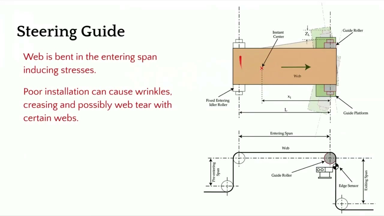
In this web guide, we are creating a bending. So there is a bending action here. It's displacing as well as bending. In terms of the entry and the exit span, there are some guidelines for that as well and we'll go through that.
This is not an ideal choice for us because it's bending. So it's introducing stress. If it's not installed properly, it can cause wrinkles, creasing, web tear, and edge stresses. In terms of installation, what do we need to look for?
We need to make sure that the exit span is perpendicular to the plane of motion of the web guide. The main thing is to make sure that the exit span is in pure twist. This allows us to have the least amount of stress in the web. So we want to do that.
Now the entry and exit span length is also depending upon the stiffness of the web. You typically need a longer entry span for a rewind guide because the motion of the web guide or the displacement of the web happens because of bending. So you have to follow those guidelines in terms of if you have a stiffer web, you need to have a longer span so that you can allow the bending to happen. Normally it's about 1 to five times the width of the web.
And then the exit span can be half a web width. And there's also minimum formula for finding out the minimum span length. In terms of other things here, let me talk a little bit about the instance center. Like I mentioned, there is a raceway, two raceways here, and they are angled so that you can have the web guide go around an arc.
And the center of the arc is called the instant center. This is important. We need to make sure that the instant center is within this span. and it's at a certain distance about half the length of the span or up to 2/3 the length of the span.
These are all numbers coming from the dynamic model of the web guide and the dynamics of the web itself. If you don't follow those conditions, then you can have a web guide over steering, under steering, creating an awful lot of stresses, maybe wrinkles, slack edges, tight edges and all those kind of things. The main things that we want to look for is this angle. Make sure that it's 90° and then you have an entry span that is pretty long.
You can have different wrap here. We don't want to go more than 45° on either side. When you do that, you're adding twisting. Uh so whenever it goes away from this 90°, it's not pure bending.
There is bending and twisting in mold there. And then we want to have an angle here because when you put bending stresses here, you have the possibility of what we call as moment transfer. So the motion of this roller can actually move the web upstream of the guide roller. In order to avoid that, we want to have certain conditions here.
And we also want this span shorter so that it becomes harder for that moment transfer to occur. Those are some of the guidelines for installation of a steering guide and again sensor as close as possible. [Music]
In this webinar episode on web guiding fundamentals, we delve into the accuracy of web guides, discussing various factors that affect their performance. We explore how steady state and transient errors can influence guiding accuracy and highlight the importance of machine quality, material properties, and proper installation. Additionally, we cover the design requirements necessary for achieving optimal web guide performance, emphasizing the need to understand conditions like web speed, thickness, and tension.
Transcript
Show full transcript (491 words)
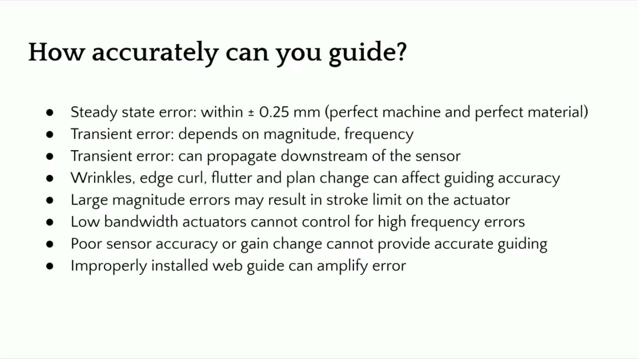
[Music] So the final question here is that you have a web guide and we talked about all these different things. What is the accuracy or how accurately can you guide a web? It actually depends. Like I mentioned, there are lots of different parameters that are going to affect the accuracy of the web guide.
If we are just dealing with a steady state error, we can expect plus or minus 0.25 mm. If you have a good machine in a perfect material, this is what you can expect. Higher accuracies are possible. Like in printed electronics, you can get much higher accuracy.
But if we're dealing with steady state errors, you have a good edge and all those kind of things, this is possible. But the problem is that most web guides are going to come into transient errors. These are either disturbances or material properties that are going to affect the disturbance in the web guide. Now, if you're trying to correct a transient error, it really depends upon what is the magnitude of the error, what is the frequency of the error and so on.
And another important thing that we need to consider is that these transient errors can actually propagate downstream of the sensor and these are called what are called as wave generation. Even though you correct it at the sensor, you don't really know the angle at which the web is approaching and that can cause weaves downstream. You won't have good guiding performance if you have wrinkles. I mean, if the web is wrinkling, that is going to cause the edge to move back and forth.
There's no way you can have good guiding performance with that. Or edge curl, flutter, or sometimes plane change can also have that effect. If you have large magnitude error and your stroke of the actuator is limited or the correction that the webgate can provide is limited then you can expect good grading performance whenever the actuator tops out on either side of its stroke. If you use a lower bandwidth actuator and you have a higher frequency error, you can expect good guiding performances and sensor.
If you don't have a good sensor or if it has gain changes then you can expect a good guiding performance and then improper installation can actually amplify the error. So that's another thing that we can expect. Anyway, so just to summarize the factors affecting we talked about a machine related, process related, material related and the web guide related which is like the stroke deadband actuator backlash correction stroke limit and things like that. So in terms of design requirements uh a good knowledge of the the the conditions like web speed location thickness stiffness environment tension side correction all of these are important for us to have a welldesigned web guide.
If you have a good understanding of all of these, we will do well. [Music]
In this installment of the Webinar on Web Guiding Fundamentals, we delve deeper into the pivotal role of controllers in web guiding systems. The episode covers the function of controllers, components such as gain, operating voltage, and sensor inputs, and explores the control structure for web guide systems, including fixed gain proportional control and adaptive control technologies. By examining open loop and closed loop responses, we highlight the importance of optimal tuning for improved performance.
Transcript
Show full transcript (917 words)
[Music] The controller is the central processor that takes the sensor input, computes the corrective action and sends that information to the actuator. Nowadays, the controllers also include human machine interface like an operator interface. Previously, the controller could be standalone. It didn't really have an interface.
So the controller could be analog in the sense of electrical analog or pneumatic analog controllers. So basically controller is taking the sensor signal and then making the necessary computation so that the actuator can be positioned at the desired location. In terms of terminology, gain is one of the most common things that you're going to hear in controllers. That's basically saying how quickly or what kind of a dynamic response you need.
gain is going to do that. Other things that you're going to see is operating voltage, power consumption, whether you have a operator interface or not. And then whether this is a controller for a servo motor or stepper motor, they have drives or drivers for it. How many sensor inputs you have?
Does it have Ethernet connectivity? Does it have remote control and stuff like that? In terms of the control structure, most control systems have webguide control systems have this kind of a structure where you have a fixed game proportional control. You really don't need more than a proportional control for a web guide because there's integrator built into it.
But usually you have something like you have a motor, it might have a current loop, it might also have a velocity loop with a tachometer. Then you have a guide structure which has its own transmission ratio. And there's the web dynamic which is unknown. Web dynamics means that if you move the guide 1 mm, how much is the web going to move?
That really depends upon transport conditions, the stiffness of the web, tension and all those kind of things. And then finally, you have a sensor that measures the edge position and then it sends that to a position controller. So this is a pretty simple architecture for most webguide controllers. They are fixed gain and most often they are d-tuned because of the stability and all the other reasons.
Most web guides their controller is kind of d-tuned for the conditions. If you want to get the best out of it, you would need to retune them. The tuning has to be based on the optimal performance because the web dynamics is unknown. Most often DC motors or DC servo motors or stepper motors are used in this kind of control structure.
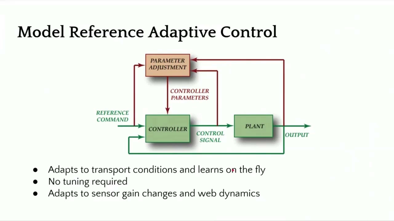
There are some other advanced control technologies like adaptive control where the controller can adapt or learn on the fly and tuning may not be required. When we say learning on the fly, it means that it adapts to sensor gain changes or the dynamics of the web. In our case, we have a similar structure as the one I showed first. It's still a fixed game controller, but with some motion control aspects built into it in terms of curving the position and having trajectories for velocity, we can increase the stability of the controller and provide a pretty aggressive output performance.
You can have a current loop, a position loop, if you have a encoder, and then a position of the actuator here. And finally, the web position, which includes the web dynamic. Just to give you an idea, we have a lot of different things that we can do with the controller. But the dynamics is basically if you move the this is showing a step response, openloop step response for a web.
This was like a non-woven web that we had at different speeds and see how it behaves. And you can see that when you have a step, even though it's open loop, it's trying to get there. The openloop dynamics is different based on how fast you're running. So faster you're running, it gets to that desired location uh as fast as possible.
But the slower you're running, it takes longer. Again, this is an openloop response. This is the final part of the whole web guiding, which is the dynamics of the web. Now if we add a controller to it then we can have a much better response and actually push the web guide.
In this case at the two different speeds that we were running at this was the reference change and this was the actual response of the web guide at the sensor. And then when we have another sensor installed once span downstream you can see how long it takes for that to go through. When we have a step response, we were able to get up to about 170 mm/s or like 7 in per second. This is about close to 70% improvement over an openloop response.
And again, this is closed loop. That means you're actually actively guiding the web. So with a proper control structure design, you can get a high bandwidth system close to 6 hertz or something like that and then even get a well damped system. So you can actually have an aggressive correction if you need to.
In terms of the characteristics of a good webg guiding system, it should have the ability to attenuate disturbances, easy to tune. Obviously, it needs to be stable, has good processing power so that it can process multiple sensors, have industrial Ethernet connectivity. These are for advanced functionalities. And then smart intelligence for industry 4.0.
[Music]

In this episode of our webinar series on web guiding fundamentals, we dive into the critical role of sensors in web guiding systems. Learn about various sensor terminologies such as range, resolution, accuracy, and linearity, and understand the importance of accurate measurement for effective control. We discuss different sensor technologies including infrared, optical, and ultrasonic, and explore the challenges they face including issues with temperature drift and material properties.
Transcript
Show full transcript (725 words)
[Music] One of the most important parts of a webg guiding system is the sensor. It is important because what you can't measure, you can't control. If you have a poor sensor and you're not able to measure the position properly, then there's no way that we can get the accuracy that we need. In terms of sensor terminologies, range, resolution, accuracy, linearity, those are some things that you would see.
type of sensors, infrared, optical, ultrasonic, air type of things that you're trying to look for in terms of web position. Are you trying to look at edge of a web? Are you trying to look for a line on the web or a contrasting feature on the web? How fast can the sensor measure?
Older ultrasonic sensors have issues with past line changes. You can't have the web too close to the ultrasonic emitter because it might reflect the sound waves in a way that doesn't provide an accurate measurement. And then temperature drift. Again, ultrasonic sensors can have issues with temperature drift when we have the P2 electric crystal frequency changes.
And then what kind of a signal output that you get from the sensor. Range of a sensor is the maximum lateral displacement the sensor can measure. Most often for web guiding applications, range is not that important just because of the fact that you're controlling. You're going to bring it in.
But it does becomes critical when you have web width changes and things like that. Most often range is like how much change in the lateral position that you can measure with the sensor. Resolution is the minimum lateral position change that the sensor can see. So if you want to guide a web to 5,000 of inch, then you better have a a sensor that can have 4x or 2x higher resolution than the guiding accuracy.
Accuracy is an indication of how close the sensor measurement is to the real measurement. This becomes important for certain types of sensors affected by materials. Material properties like opacity, porocity and things like that. This is an important characteristic of a sensor.
Linearity is like what how consistent is your measurement with respect to the actual position across the entire range of the sensor. In terms of sensing, why is it important? Some sensors have issues with material properties like opacity, porocity or reflectivity or they may be affected by environmental issues such as air flow, temperature changes or vacuum. So if we can't measure, we can't control.
That's why sensing is an important part of guiding performance. Most often you would see these type of sensors we refer to as opposing beam or fork style or horseshoe style. There are lots of different names for it. Basically how this works is you have one arm emitting a certain type of signal and the other arm receiving that signal and then the web that goes in between blocks it.
It's a simple technology work sensing principle and it works well for a lot of different cases. The problem happens whenever depending upon this type of sensor signal that you have if the web allows that signal to leak through when it's blocked by the web that's where the pro problem occurs. We talked about linearity resolution range all of those things are affected by this kind of sensor. This sensing signal can be air, optical like visible light, infrared lights, or even UV light.
It could also be sound like ultrasonic. It really doesn't matter. And then whether this material is opaque or porous to that signal is what matters in terms of how well you can guide. Often manufacturers recommend different sensors for different materials and conditions.
So you will have a plethora of sensing technologies out there. Like I said, the main disadvantage is material dependent gain change occurs and then requires calibration if you want to get a really good guiding performance. There are other sensor technologies out there like ours which are not affected by material properties and some of the environmental conditions. I'm not going to go into detail about our sensor technology here but just give you a quick overview.
is basically a high accuracy direct measurement or absolute measurement. Our resolution does not depend upon the range and it can work with any material. [Music]

Explore the essential aspects of actuators in web guiding systems in this episode of our webinar series on Web Guiding Fundamentals. Discover the various types of actuators, including pneumatic, hydraulic, and electromechanical, along with key terminologies such as thrust, correction speed, and backlash. Learn about the significance of actuator sizing, web speed, and the impact of gravitational effects. Ideal for anyone looking to deepen their knowledge on steering guides and actuator functionality in modern web handling systems.
Transcript
Show full transcript (742 words)
[Music] So in terms of actuators, there are lots of terminology that is involved. Some of them are thrust or power, how fast the accelerator is, what is the correction speed, what is the acceleration, stroke length, mounting, what type of coupling we have and things like that. Actuators are pretty standard right now. It's not as important as installation of a web guide or the sensor, but it is an important part of a web guiding system.
The older actuators were either pneumatic or hydraulic. You had an hydraulic pump pumping a double acting cylinder and moving the web guide structure. These were more common in the 50s and up to about maybe '90s before the electronic electromechanical actuators started coming into the market. You could have pneumatic actuators or hydraulic actuators.
The hydraulic actuators have the advantage that it can provide high thrust and can shift large loads quickly. Even now in metals industry, hydraulic actuators are pretty common. You can see them. But the problems are that it's a problem with maintenance.
You need to balance the valves and stuff like that. Change the filters. They could cause leak and this could contaminate your product. And then the precision and accuracy that you can get with an electronic actuator or electric actuator is not something that you can expect in an hydraulic actuator.
So most web guides nowadays are going to use actuators like what these actuators usually have a motor that drives a belt pulley system. There's usually a lead screw, a ball screw or a roller screw that converts the rotary motion into linear motion at the end of the actuator. Some common terminologies that you would see with actuators are maximum current, voltage, power. Whenever we have something with a lead screw or a pitch, that's a common term.
What is the lead of the actuator? Pitch of the actuator. Gearing ratio. Backlash is another thing that you would commonly see with electric actuators, especially with low-end lead screw actuators.
Resolution. What is the smallest movement an actuator can produce? Back drive is a common terminology especially if you're installing a web guide that has to work against gravity. And then types of actuators you have inline and reverse parallel.
Some actuators have limit switches or end stops. And then type of motor used in the actuator. You would commonly see servo stepper brushed or brushless DC motor. So actuators are providing the driving force to the guide structure so that it can position the web.
In terms of thrust, the thrust is the amount of force exerted by the actuator to move the guide structure. And this thrust really depends upon as we saw before mass of the structure that we are trying to move, what is the friction there, how fast you want to move and sometimes gravity as well if you're acting against gravity. In terms of sizing actuators, these are some of the things you need to know to size an actuator properly. a web blind speed mainly because if you have a slow moving web the maximum disturbance frequency you can get depends upon the speed of transport of the web.
If you're moving at 100 ft per minute you might not need a high dynamic response while if you're moving at high speed you might need a much higher dynamic response. The dynamic response is related to the acceleration. Acceleration is related to the thrust. So that's why line speed becomes important.
Guide structure weight and roll weight. If you're trying to move a big mass, we need to know that what type of bearing you're using. So that what is the breakaway force that we need to overcome based on the coefficient of friction of the bearing and then what kind of disturbances we are trying to correct for. There is a correlation between the amount of disturbance that can propagate through a roll-to-roll machine that really depends upon the speed of the web.
The faster you go, higher frequency disturbances can go through. So the web acts as like a low pass filter and then the acceleration and then if you have to look at any gravitational effects. These are some of the key factors that are involved in properly sizing an actuator. But like I said, actuators are pretty straightforward nowadays.
Just need to have some basic questions answered and then we'll be good to go. [Music]
In this episode of the webinar series on web guiding fundamentals, we delve into the critical aspects of steering guides. Learn why it's crucial to maintain a 90-degree angle on the plane of motion to avoid twisting and bending in the web span. Discover the ideal range for raceway angles and the importance of considering web stiffness and entry span length during installation. Proper installation processes are key to minimizing errors and avoiding the common pitfalls that can lead to increased costs and amplified inaccuracies.
Transcript
Show full transcript (467 words)
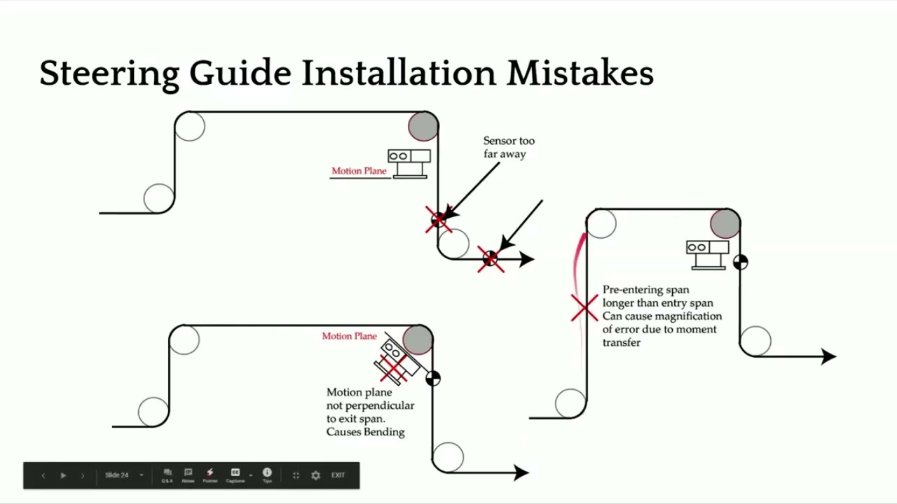
[Music] Now, what not to do? Same thing. We don't want to put the sensor too far away. One of the things that is not really evident is that we don't want to put the plane of motion of the web guide at anything other than 90°.
It's not this angle between the entry and the exit span that needs to be 90°. It's actually the angle of the plane of motion of the web guide and the exit roller. That's what determines whether you're going to have a twisting action or not. When you have something like that, you're going to introduce bending in the span.
And when you start bending a short span, it's not a good sign. So, we don't really want to do that. So, that's the main reason why we need to have the plane of motion perpendicular. Not really the entry and the exit span, but the plane of motion.
And then like I mentioned, if you have the entry span and the pre-entry span longer than the entry span, then you could have moment transfer happening. That's something that you don't want to do either. In terms of wrap angles, pretty simple. You can have something going up like that or going down like that.
As long as we follow this condition, that exit span is perpendicular to the plane motion, then we are in good shape. Just to summarize the design consideration, design correction is one of the main things there. And the raceways that we have on the steering guides, we don't want to angle them more than 25°. So anywhere between 5 to 20° would be the ideal one.
In terms of installation, steering guide is a lot more complicated to install. You have to consider the stiffness of the web, the entry span length. You need to make sure that you're not putting too much bending stress on the web based on how stiff your web is, the location of the instance center, which depends upon the raceway angle, depends upon the length of the entry span. So, there are lots of things to consider for proper installation of a steering guide.
These web guides are prone to have a lot of issues because they're not properly installed. In terms of advantages, they're they're simple, so they're cost effective. It's just a single roller. So, it's inexpensive, but it comes with other things that increase the overall cost of ownership.
It's hard to install. A lot of attention to detail is required, especially because of the bending and things like that. Loss of traction or anything like a moment transfer occurring can actually amplify the error. So, a poorly installed or poorly designed steering guide can actually produce error, more amplify the error than than what it's intended to do.
[Music]