In this episode of our webinar series on web guiding fundamentals, we explore the installation and operational intricacies of a steering guide. We cover the mechanics of a single roller installed on angled raceways, its bending action, and essential guidelines for entry and exit spans. We discuss the importance of maintaining a 90-degree exit span angle to minimize stress and prevent issues such as wrinkles and web tear.
Transcript
Show full transcript (631 words)
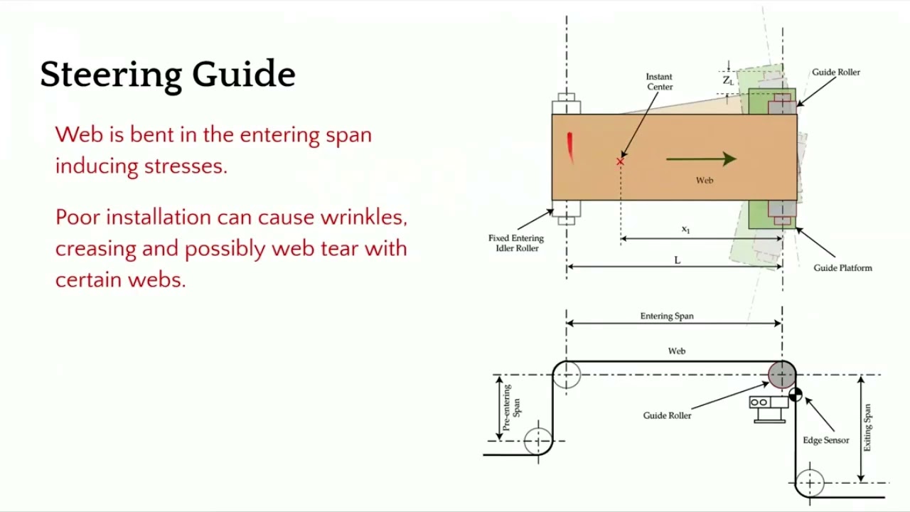
[Music] The second choice for us would be a steering guide. In terms of how it works, it's a little bit different. You got a single roller. This is the top view and this is the side view.
This roller is installed on two raceways at an angle. The web guide forms an arc like that. It moves and forms an arc back and forth. That's how we are changing the axis of rotation.
In this web guide, we are creating a bending. So there is a bending action here. It's displacing as well as bending. In terms of the entry and the exit span, there are some guidelines for that as well and we'll go through that.
This is not an ideal choice for us because it's bending. So it's introducing stress. If it's not installed properly, it can cause wrinkles, creasing, web tear, and edge stresses. In terms of installation, what do we need to look for?
We need to make sure that the exit span is perpendicular to the plane of motion of the web guide. The main thing is to make sure that the exit span is in pure twist. This allows us to have the least amount of stress in the web. So we want to do that.
Now the entry and exit span length is also depending upon the stiffness of the web. You typically need a longer entry span for a rewind guide because the motion of the web guide or the displacement of the web happens because of bending. So you have to follow those guidelines in terms of if you have a stiffer web, you need to have a longer span so that you can allow the bending to happen. Normally it's about 1 to five times the width of the web.
And then the exit span can be half a web width. And there's also minimum formula for finding out the minimum span length. In terms of other things here, let me talk a little bit about the instance center. Like I mentioned, there is a raceway, two raceways here, and they are angled so that you can have the web guide go around an arc.
And the center of the arc is called the instant center. This is important. We need to make sure that the instant center is within this span. and it's at a certain distance about half the length of the span or up to 2/3 the length of the span.
These are all numbers coming from the dynamic model of the web guide and the dynamics of the web itself. If you don't follow those conditions, then you can have a web guide over steering, under steering, creating an awful lot of stresses, maybe wrinkles, slack edges, tight edges and all those kind of things. The main things that we want to look for is this angle. Make sure that it's 90° and then you have an entry span that is pretty long.
You can have different wrap here. We don't want to go more than 45° on either side. When you do that, you're adding twisting. Uh so whenever it goes away from this 90°, it's not pure bending.
There is bending and twisting in mold there. And then we want to have an angle here because when you put bending stresses here, you have the possibility of what we call as moment transfer. So the motion of this roller can actually move the web upstream of the guide roller. In order to avoid that, we want to have certain conditions here.
And we also want this span shorter so that it becomes harder for that moment transfer to occur. Those are some of the guidelines for installation of a steering guide and again sensor as close as possible. [Music]
In this episode, we explore how to utilize the center guiding feature of the SCU6x Controller with two sensors, focusing on automatic adjustments and setup. We demonstrate the mechanics of center guiding using an actuator and explain the importance of using sensors of the same range. With detailed visuals, we show how to reset the guide point and align the material to the center of the machine.
Transcript
Show full transcript (1038 words)
So, one of the other things with the SC6X controller is that we can do center guiding with two sensors and it can be done automatically. We talked about how to set up the different sensors for different configurations. So, please take a look at those videos. In this video, we're just going to show you how it works with an actuator, how things look, and how to reset the guide point for center guiding.
What we have is a couple of sensors connected here. One of the things with center guiding is that we would like the two sensors to be of the same range. Even though the system would work when you have two different ranges just on the display to make it simpler and not cause any confusion, it's better to use two sensors of the same range. Right now, I have an infrared sensor and a white light sensor just for illustrative purposes.
In reality, anytime we are doing edge or center guiding based on the edge of the material, we're going to always use an infrared sensor. So, let's go back to the screen and see how it looks. This sensor is set to see the left edge and this sensor is set to see the right edge. So, if I have a material that is presented, you can see that it's seeing the left edge and the right edge.
The green in the middle is showing the center line position. And in this particular case, we got the guide point offset to be zero. So if I set it to automatic, then the actuator is going to move back and forth based on if the center position is within the guide point to the left or to the right. And that's essentially how the center guiding works.
There are two main reasons why somebody would use center guiding. One is if you're changing web widths and you want to align the material to the center of the machine, then center guiding is the best option where you would place two sensors on either side and the those sensors are equidistant from the center line of the machine. So when the web width changes, you don't ever have to move the sensors and it automatically adjusts itself because it's going to look at the left portion of the web seen by the left sensor and the right portion seen by the right sensor. This is one of the common features that we have or common value proposition from our products is that our sensors can go anywhere from 48 mm up to 960 mm.
That means you can have a width change of about 96 mm up to about 1920 mm without needing to move the sensor. This provides a lot of range and flexibility to be able to have a system that can adapt to wick changes on the flight. The older generation systems might have some actuators that move the sensors based on the wick change. And more often than not, what happens is that those actuators have their own control loop that needs to be tuned.
The actuators can wear. These are the actuators for the sensors that could wear over time. And that creates an issue. And then the response time, especially when you do a wid change on the fly with those kind of systems, is going to be much lower than compared to a system with a sensor that is wide enough to cover all the width changes.
So that's one of the main reasons for using center guiding is that you can do different widths without moving the sensors whenever the width changes. The second main reason why you would use center guiding is that let's say you have an edge especially some kind of an extruded edge and the edge quality might not be great. So before it goes into a slitter you you have an edge and the edge is not that great. Instead of aligning to one edge of the web, in that case if you use two sensors and then use the center line position, it takes the average of the left edge and the right edge and does the measurement that is going to be the center line measurement and it's going to guide the web to the center.
This is one of the biggest advantage for using two sensors and doing the center guiding and especially when you have irregular edges, those edges variations are not going to be identical on both sides. This smooths out your edge profile and allows you to guide the web in the middle of the machine and that significantly improves the wound roll quality especially if you don't have a pretty good slit edge. So the advantage is that you are averaging based on two edge measurements and this helps in smoothing out the edge position. Those are the two main reasons why you would use center guide.
One of the other things that I want to show with center guiding is that you can do the reset guide point just like what we did with edge or center guiding with two sensors. Let me show you that. Going back to the screen here, we have the web now and the green position indicates the center line position. If the web is moved that way and for whatever reason you need to do that, you could do the same reset guide point and accept.
Now the guide point offset is there. If the edge position goes on either side, the actuator changes its direction back and forth. This is for doing the center guiding with the point offset. Now, like I said, it's not usual for you to change the guide point offset with center guiding just because you want the material to be aligned to the middle of the machine.
The reason why we allow you to do that is that let's say you had not installed the sensor at the right location to begin with. Instead of going and physically moving the sensor, you could just move the offset. And that's the reason why we allow a guidepoint offset even when we do center guide.
AIMCAL R2R 2020 Conference: Advanced Web Guiding Applications and Concepts
Transcript
Show full transcript (5014 words)
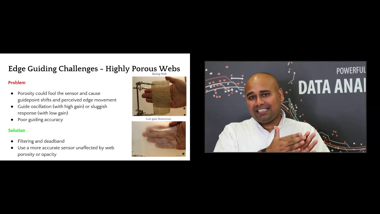
good morning everyone this is aravind se chadri from roll to roll technologies i'm here today to talk about advanced web guiding applications and concepts before we begin let's look at some of the basic concepts regarding edge guiding center guiding sensor positioners moving sensor center guide what do we mean by guide point what do we mean by remote guide point uh what is a dead band and what is edge filtering we will use these concepts to build on so that we can look at how some of the challenging guiding applications can be solved uh by uh some of these things that we initially cover so uh everybody is familiar with edge guiding if not edge guiding or guiding basically is to align the cross machine direction position of the web within a roll roll-to-roll machine so you're laterally positioning the web at a certain location in the cross-machine direction of the web this is typically done with a single sensor and the sensor measures the position of the web and sends that information to a control system and uh based on the measurement and the reference there's an error that is computed and then the control system sends the command to the actuator and then the mechanism uh the web guide mechanism moves the web and then this is a closed loop control system that keeps going on typically one sensor or two sensors are used and in a single edge guiding application the sensor may be installed on the drive side or on the operator side depending upon what is required and then the sensor is typically positioned at a constant or a predefined uh reference within the machine so that the web can be guided uh to a certain position within the machine now the main issue with a single sensor web guiding application is that um whenever the web width changes then somebody has to go move the sensor and uh depending upon your process uh if the process is aligned to the center of the machine or if it's justified to one side of the machine the sensor might have to be moved at different locations and any time when you have to move a sensor that causes downtime and it also introduces an opportunity for error and operator error so that's the main issue with edge guiding with a single sensor and and apart from edge guiding there are some situations in which center guiding is used where you have two sensors each of them looking at one edge of the web and then they send the signal to the controller and the controller averages those two measurements and then based on that average measurements it computes the error and then it moves the actuator based on the error the main reason why the center guiding is used is in applications where there is an inherent possibility of a slight variation in the web width let's say you have an extrusion process you're extruding the web but it's not a a straight edge it might have some amount of variation there to reduce the effect of either justifying to one side where you you might have a perfectly round roll on one side and then a really jagged uh raw uh edge on the other side it's common for um manufacturers to use two sensors to center guide the web now even with the center guiding application when the web weight changes uh somebody has to move the sensors and again like um a single sensor you need to move it at the right location and now you have two sensors that needs to be moved and then these two sensors have to be positioned exactly equidistant from the center line uh all of these causes time and if there is an error then it causes downtime as well so in order to avoid this some manufacturers have what is called as automated sensor positioners instead of manually moving the sensor you can automate that by connecting an actuator to the sensor and you can move one or two sensors based on what product you are running and you can automate it by setting all of those into the plc so that based on the product code the sensor is moved automatically this does reduce the downtime and then it also helps reduce the operator error but this system is a little bit complicated um because you have a system lan an actuator it needs another control loop to move the sensors and if those sensors have to move automatically without an operator kind of pressing a button to get it to the different location then you have an additional control loop in there and that increases the complexity of the system and then when you have an additional control loop you also need to tune the control loop so if the web width kind of varies like like this and if the sensor is automatically moving it's oscillating back and forth then the gains of those system has to be uh adjusted just right so that it doesn't never miss the web and then it's not too aggressive that it can run into the web and damage the web so this increases complexity additional actuators additional drives that are involved and overall it adds more mechanical wear and tear to the system um a better way of doing this is to just have a white sensor uh if your sensor is wide enough to accommodate any web weight variation then there's never ever a need to move the sensors and you can put one sensor on each edge so you have a center guiding sensor center guiding application with two sensors and with the web width varies and if the sensor is wide enough to see all of the variation then you would never have to move the sensor and you can still do that one of the key things in accomplishing accomplishing this is uh basically what we call as a guide point so when you have a single sensor and you're guiding the web uh based on the measurement from the sensor the control system is going to use a reference signal and that reference is usually the middle of the sensor's position measurement so if the sensor has an output of 0 to 10 millimeters and 5 millimeter for example would be the reference and if the web goes at four millimeters or if the web is at six millimeters then there is an error that is being created based on the magnitude and the direction of the error the uh control system sends the command to the actuator to move the web guide and most most often the guide point or the reference is in the middle in this case it's 5 like what i mentioned now instead of moving the sensors manually what can be done is actually move the reference within the sensor so instead of guiding to five millimeter when the web weight changes you can guide to two millimeter as the reference so if the web is at one millimeter it creates a negative error and then when the web is at three millimeters it creates a positive error and now your guide point is moved to two millimeters and this is what is called as an electronic guide point change the main advantage with the electronic guide point change is that if you have a sensor that is pretty wide and let's say you have a sensor that is 17 inches wide then any web width variation you don't have to move the sensor so that the web can be guided to the middle of the sensor you can just electronically move the guide point to a location so that the web can be guide at that location and this is a simple uh thing that can be done it's easily it can be automated easily and then you don't have any mechanical wear and tear because everything is fixed and you never have to move the sensor and this is what is illustrated in this uh animation here where if the guide point is to the left or to the right then the the reference for that control system uh is going to be at that location and then the actuator is going to change direction at that arbitrary location so you can technically have the guide point anywhere within the sensing window uh but it is very common to limit the extremes um so that you don't put your guide point all the way to one edge or all the way to the other edge the main reason is that once the web moves past that edge irrespective of where it is it's hard for you to know what's happening there so you you want a little leeway so that you don't go all the way to the extreme on either direction so uh it could be like you can go up to 90 of the sensor range that's where the guide point can be changed uh but within that remaining five percent on either side you cannot change the gate point uh so this this is what is called as an electronic guide point change and it's very common especially with a wider sensor and this enables operators to not to move the sensor and have a quick product changeover and then when we do center guiding the guide point change actually doesn't you don't need to do a guide point change when you do center guiding especially with two sensors and that's what this map is showing is that even if you move the sensors uh on either direction the guide point doesn't change so this is making it a lot more simpler so center guiding with two sensors is a lot more simpler than uh edge guiding and then even when the webwork changes you never have to change the uh guide point so these are the advantages like i mentioned center guiding with the white sensor is a lot more simpler reduces uh the mechanical wear and tear inherently it averages so that's like a filtering and then it's a simple to install operate and then helps you with the quick product changeover and then you can use this sensor to as a web detect sensor and as well as to monitor the width of the web because you can see both edges of the web another concept that is commonly used is what is called as a dead band a guide point is the reference from which the the the uh error sign changes now dead band is a region around the grade point where we can still say the error is zero and then uh beyond the deadpan is when the error becomes paused toward negative and uh this is done mainly to avoid any issues with uh artificial uh edge position variations that are created by edges that are kind of fuzzy or rough where the web is actually not moving just that the edge is kind of jagged in order to avoid the web guide from moving back and forth we can use a dead band onto it and finally a concept called edge filtering it's basically uh instead of taking the measurement instantaneous measurement you can filter the data uh in time and a typical filter that is commonly used is an exponential moving average filter and this helps in significantly reducing the variation of the edge position especially when you have some kind of an edge that is jagged and it's not really representative of the actual web position but just that the edge is kind of jagged like that this plot is just showing how if you have a standard deviation of 7 and then if you do a filtering for example you can reduce that variation by 50 and then if you do an averaging with that you can reduce that even further so the top plot is showing the measurement from one sensor the bottom plot is from another sensor and then the middle plot is the average of those two sensors that would be the center line center guiding kind of thing uh so some looking at some examples um let's say you have an edge like this um the web is pretty uh jagged and this is from an extrusion process now you don't want to take the instantaneous measurement and guide the web because the web guide is going to be oscillating back and forth it's going to be crazy what better way to do this is to use two sensors so you get an inherent averaging of those two edges and then add a dead band basically if you have an idea of the profile of this edge that is varying based on that you can create a deadband value and then filter the edge position so that the the steady state or the gross position of the web would be at a fixed location then even when the edge measurement is not that great you can still have the web guide to not oscillate um instead of there are situations where you deliberately have an edge with a certain profile like what is shown here and it's got a sawtooth kind of profile the main problem with this is that none of the conventional techniques would work because that when this web goes underneath the sensor and you're looking at that edge position depending upon the speed depending upon the sensor measurement frequency and depending upon the duty cycle of the sawtooth wave when you do any kind of an averaging you're going to shift the guide point you're going to have that average move whenever any of those conditions change for example let's say you're running a thousand feet per minute and you do all of these things and then now you go to uh 2000 feet per minute that's going to cause a shift even if you do any kind of an averaging so temporal averaging or time based averaging is not a solution for that but a spatial averaging or spatial filtering is a solution in this case you would align the sensor vertically along the machine direction and then have some kind of a like a bang bang control to be able to guide the web this is a technique that we use to guide some of these webs like this another common problem that we would see is uh wrinkles uh basically what uh wrinkle is that whenever there's this trough and the valley that is created on the web it's going to suck the edges in and out in and out in and out based on how the wrinkles are flowing and this is going to cause an edge position variation which is not representative of the web position the edge may go in and out but the web may be still in the grass position so this affects a lot of systems and the best way to tackle this is to do center guiding and based if you have any information about the wrinkles you can have that use that in your infinite impulse response exponentially moving average filter to reduce that effect and then also use a deadbend so depending upon how much the width variation is you can put that into your system so let's say the wrinkle is causing the width to change by a millimeter then you can have half a millimeter of deadband on either side and that would make sure that the wrinkle is not causing the web to oscillate but in reality these are all kind of like a fixes and these are not real solutions for the wrinkle problem and in this case you have to go and fix the underlying wrinkle problem but to avoid the web guiding from oscillating these are some things that we could do and finally uh there are situations where especially in diaper manufacturing or non-moments where you're running a porous web and then the sensor that you're using to run the porous web is affected by the porosity of the web and what it essentially would do is depending upon the density of the web underneath at that instant when the sensor is making the measurement that's going to change your output of the sensor so the output of the sensor may be varying based on the density of the web at the instant that you are measuring this will cause an artificial variation in the edge position which is unwanted and the best way to avoid this is to use a sensor that is more accurate that is not affected by porosity variations and density variations and if you cannot do that then the the other best way to do it would be to do some dead band and filtering and depending upon how much accuracy you can achieve so whenever you add a dead band and filter you are reducing by adding deadband you are reducing the accuracy that you can get and then by adding filtering you are reducing the dynamic response or how fast your uh system can correct that error you are reducing those so it's a trade-off based on uh what is uh what is the ultimate objective and this is just an illustration kind of showing like when you have an artificial edge position variation and then when you do a center guiding you can see that the middle plot is the set the top plot is one sensor the bottom block has another sensor and then when you do a center guiding where you take the average of those two just by doing that you you're reducing the variation and then if you add a exponential moving average filter to it you're reducing it further and then if you add a deadband to it then you are reducing that even further so this is shown in this table here and you can see we start off with about one millimeter of standard deviation and then by just by filtering we got about 40 improvement and then if you do filtering exponential moving average and dead band you get about 70 percent reduction in the variations and again these variations are artificial so um the dead band and the exponential moving average uh the filter time constants have to be designed based on that information that hey how much is the variation and things like that all of these can be avoided if you use a sensor that is not affected by any of those uh finally the the uh whenever we are looking at uh guiding a web there may be situations where you might want to guide multiple webs um and this is true in lamination or coding or extrusion lamination any of those scenarios in those cases you can typically guide two layers of the web independent of each other and then guide it to the same machine reference then you can achieve a proper lamination at this point but the main problem with that is when the web weight changes or if there's uh any centerline guiding uh kind of application then you need a little bit more uh coordination between these two systems these two layers the web one of the things that has been done mechanically is to chase the web and in that case you have a web master web that is there and then there's a sensor that is installed to chase the web it means that if the web moves uh one inch on one side the sensor would actually follow and chase the web so there's a control system that is kind of chasing the web and that particular sensor is connected to the other sensor on the other layer and this basically means like okay if the web moves on the bottom one inch i'm going to move my sensor one inch on the top and this is done automatically so there is a control loop that is uh moving the sensor positioner mechanically obviously you can see that it's a complex system there's too many mechanical parts and then depending upon how far these are then the mechanical coupling is going to be an issue and then if you want to do center guiding with this kind of system then it just the complexity goes pretty high pretty quick a better way to do it would be to use the guide point or the electronic guide point adjustment so you do have a sensor in the bottom the master sensor that is going to look at the position of the master web and then it's going to provide a guide point adjustment to the sensor on the top uh so that whenever the master web moves the top guide point of the top web sensor also moves and that makes sure that these two webs are coordinated if you have multiple webs uh multiple layers then we do the same thing as what we did in the in the in in the previous example the only other thing is that there are two now two different web guide uh sensors uh whose position needs to be varied so this is accomplished by slaving one of those so this is a slave actuator um and this is the uh the master actuator that is connected to this chasing sensor that is looking at the master web um this you would see uh commonly in metal industries uh in lamination processes uh again it's pretty complicated uh especially mechanically and then the synchronization it's a common problem synchronization meaning that one actuator has to be exactly synchronized with the other actuator otherwise this causes uh issues with the performance and then any lag or a slow response in one is gonna provide a overall uh worse response for your system uh the better way to do it would be to use an an electronic guide point adjustment i just used one sensor that's going to monitor this master web and then change the guide point of the other slay webs or the follower webs so that you can guide the web to that location now the main considerations with coordination is that if you have this master sensor wide enough then you can have the sensor basically look at any variation of the master web and the master in the examples that we showed there the master sensor was just used for measurement but technically you can also have a web guide on it and that web guide is going to guide the web uh on the master web and then that measurement can also be used to change the guide points on the slave or the follower webs that can be done as well and usually uh this has a good result if if we can have the web path links with these different sensors and web guides from that sensor to where the lamination process is if the web path links are the same and that provides the best results especially with dynamics and things like that but if you can't then you can use some kind of a feed forward term to compensate for the additional spans that you have to work with and then you can also do a dead band or a feed forward offset in these kind of things if you have to really put the sensor farther away from where you need to guide it so that's uh a quick overview of some of the uh things about common things irrespective of what kind of a control system that you have some advanced way of guiding concepts now we'll talk about some of the common control systems that are there in web guiding systems we're just going to quickly go through some of these things most often this is not addressed quite a bit but we're going to take a quick job at it and then there are basically three main kinds and then most of the web guides that are available in the market are fixed gain control systems and they are feedback control then proactive control is a new concept which is kind of like the future of web guiding so in a fixed gain web guiding control system as the name suggests the gain is fixed and like i said a lot of people don't really know what's inside a web guiding system there are multiple loops there's a current loop there's a velocity loop there may or may not be a position loop and obviously there's the outer edge position loop uh all of these loops have gains and these gains have to be tuned and the main problem is that this web dynamics term right here and that depends upon how fast you're running what is the tension what kind of elasticity of the web that you have how is the web guide installed all of those influence that and then anytime you have a product changeover that can significantly change any of these dynamics then the controller has to be tuned otherwise it's not going to provide a good performance most often most web guides the controllers are not well tuned that's a problem now to overcome some of these there are some other techniques called as adaptive control the main idea behind that is instead of having a fixed gain control system uh you have a controller that adapts and it learns uh based on the current conditions and it can avoid any sensor gain issues like the porosity issue that we talked about before it can overcome those it cannot adapt to the mechanical dynamics like the motor response and things like that and also the mechanical advantage of the web guiding system all of those things can be adapted too and this is a little bit more advanced control system and this this is something that is also available another way of doing this is called optimal control in this case uh what it's done is uh if you know different conditions in which your web guide is going to be operated under with what all the different materials that you're going to run all the different transport conditions and all different installations if you have to then an optimal uh controller a fixed gain controller can be designed uh so that it works best under all of these different conditions and the optimal not just means in the control system but also in the transport conditions uh the installation and things like that so this is also available i don't have a reference there in the bottom but you can look at optimal web guiding on google search and you would find papers about this there and finally uh there are other control systems especially those used in rolls-roll products is what we call as a non-linear trajectory control in this case we control trajectories for position loop velocity trajectories and also have a predictive component to it and essentially it provides you with a pretty good response uh system which is well damped and in this case we could achieve up to about 135 145 millimeters per second correction which is kind of unheard of in the industry and finally this is kind of the future of web guiding and this is what we call as proactive control instead of reacting to the edge position variations uh can we be proactive about it and this is something that we do and one of the things to hear the key thing here is that we have to first construct a performance index and then see whenever the performance index changes what are the deterrents or what are the things that are affecting that performance index is there a pattern to it and from that pattern can we see what is the root cause let's say there is an uh roller or web guide that is misaligned upstream can we detect that and then can we provide that information to the operator so that they can go in and fix that problem rather than trying to react to it an offset in a upstream process will actually limit the actuator stroke on the web guide in the downstream process and this is unnecessary if you can detect it and that's the whole idea behind a proactive control it could be offset there or a sinusoidal disturbance or any of those kind of things where it could be material process or machine and a product of control system would be able to identify and provide some solutions for it so in summary um some of the advanced web guiding concepts that we saw uh that the simplest thing that anybody can do to get a good guiding performance is to do center guiding and center guiding with wide sensors would significantly simplify your operation if you need to do dead band or if you need to do edge filtering especially you have some harder materials you can do that but essentially have a sensor that is unaffected by material property variations that will help you coordination can be achieved with electronic guide point adjustment and then the future is in proactive control do not react to the problems be proactive and kind of figure out what is the underlying cause for it and how that can be fixed in your machine that's my presentation thank you for my for your time there are some additional resources here and also my contact information um and how you can reach me unfortunately i would not be available for the q a session but i've asked one of my colleagues to be there so hopefully if you have any questions you would be able to address thank you so much for your time have a great day
Different terms related to web guiding are discussed in this article.
Web Guiding
Web guiding is the process of regulating the cross machine position of the web while the web is transported over the rollers in roll-to-roll processing machinery. Other terms for web guiding include: